Understanding Series Resonance in High-Voltage Testing: A Practical Approach
High-voltage insulation testing is critical for verifying the reliability of power cables, transformers, GIS, and substation systems. One of the most effective methods is AC series resonance testing, which leverages the principles of electrical resonance to generate high test voltages efficiently and safely.
What Is Series Resonance in High-Voltage Testing?
Series resonance occurs when the inductive reactance of a reactor equals the capacitive reactance of the test object, forming a resonant circuit. At this point:
The circuit impedance is minimized
Voltage across the equipment under test is maximized
Input power requirements are significantly reduced
This principle allows testing long cables or large-capacitance equipment without requiring oversized AC transformers.
How Does Resonance Improve Testing Efficiency?
The resonance condition creates a high-voltage boost with minimal energy input, circulating most energy between the reactor and the test object. This leads to:
Reduced power supply requirements compared to traditional AC testing
Compact and modular system design
Enhanced portability for field operations
By adjusting the frequency, operators can match the resonance point for different cable lengths, transformer capacities, or GIS equipment.
Why Safety Is Improved With Resonant Testing?
Unlike conventional AC testing, series resonance systems offer natural protection against flashover:
Automatic detuning occurs instantly if insulation breakdown happens, reducing fault energy
Multi-layer protection from overvoltage, overcurrent, and flashover prevents equipment damage
System response times in milliseconds safeguard both operators and test equipment
This combination of physical resonance and electronic protection provides reliable, repeatable testing while maintaining high safety standards.
Key Advantages for Field and Laboratory Testing
Energy-efficient: Only compensates for losses instead of supplying full load power
Portable: Modular reactors (e.g., 45kg each) allow onsite assembly and flexible series/parallel combinations
Accurate: Adjustable frequency and high-quality sine wave output ensure reliable insulation measurement
Versatile: One system can test 10kV–110kV cables, transformers up to 120MVA, and GIS systems
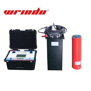
Systems like the RDXZ-270kVA/270kV AC Series Resonance Variable Frequency Withstand Voltage Test Device are built around these principles, providing both flexibility and operational efficiency.
Typical Applications
| Test Object | Voltage | Max Length / Capacity | Test Voltage |
|---|---|---|---|
| 10kV Cables | 10kV | up to 3km | ≤22kV |
| 35kV Cables | 35kV | up to 1km | ≤52kV |
| 110kV Cables | 110kV | up to 0.2km | ≤128kV |
| Transformers | ≤120MVA/110kV | — | ≤160kV (45–65Hz) |
| GIS / Substation | 110kV | — | ≤265kV |
FAQs
Q1: How quickly does the system respond to flashover?
Voltage drops and the system shuts down within milliseconds, protecting both equipment and operators.
Q2: Can it test long-distance cables and large transformers?
Yes, up to 3km for 10kV cables and transformers up to 120MVA/110kV.
Q3: Is high input power required?
No. Resonant technology significantly reduces energy requirements.
Q4: Can it handle GIS and substation equipment?
Yes, it is designed for AC withstand testing of GIS, busbars, and substation systems.
Q5: How does frequency adjustment improve testing?
Adjustable frequency ensures resonance matches different equipment capacitances, improving test accuracy and efficiency.
By integrating the principles of series resonance with modern variable frequency and modular reactor design, the RDXZ-270kVA/270kV system provides a safe, efficient, and versatile solution for high-voltage insulation testing across a wide range of equipment.
Click to know more specifications about RDXZ-270kVA/270kV AC Withstand Voltage Testing System.