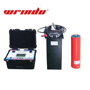
AC Series Resonance Variable Frequency Withstand Voltage Test Device

- Wrindu
- Shanghai, China
- about 20 working days
- 500 set/month
- RDXZ-270kVA/270kV
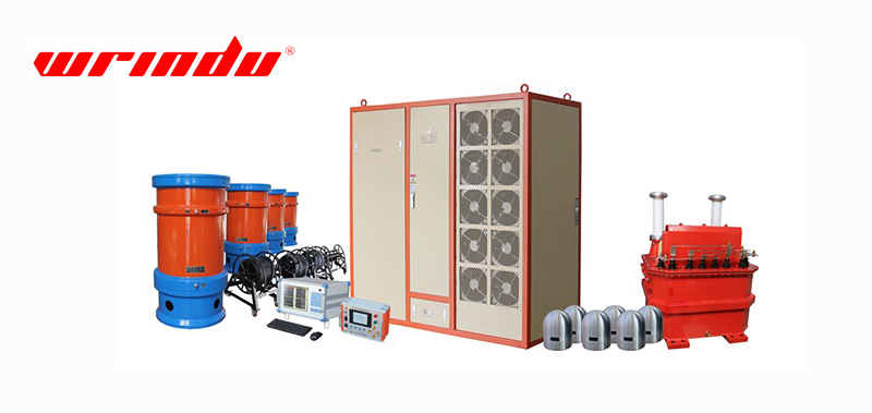
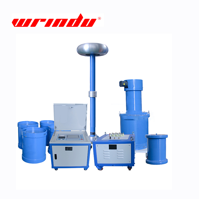
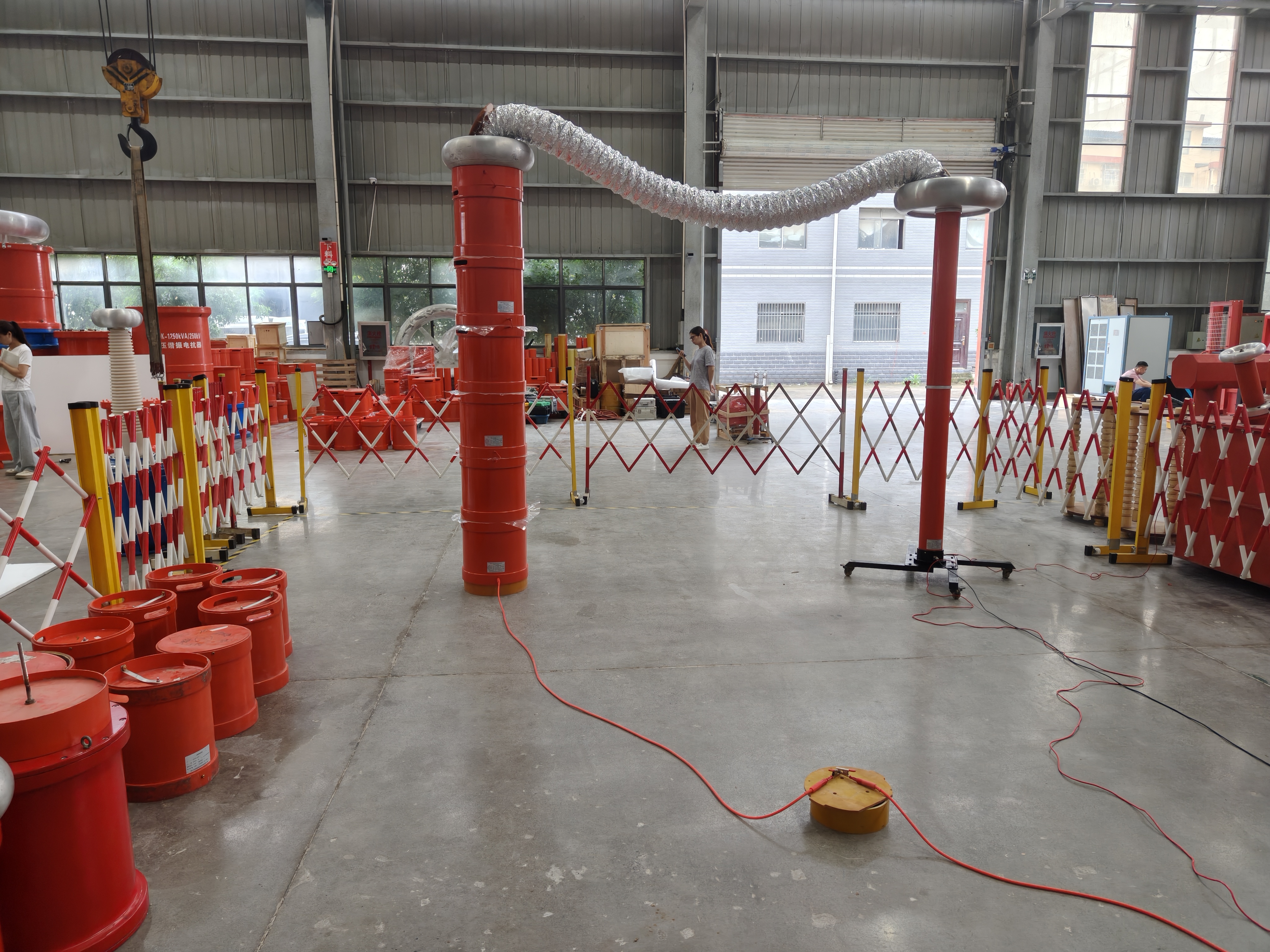
The AC resonance test system is designed for a wide range of high-voltage withstand voltage testing applications. It can perform AC withstand voltage tests on 10kV, 35kV, and 110kV power cables, supporting cable lengths up to 3km, 1km, and 0.2km respectively. With an adjustable frequency range of 30Hz to 300Hz and a maximum test voltage of 265kV, the system provides flexible and reliable testing for various cable and electrical equipment requirements.
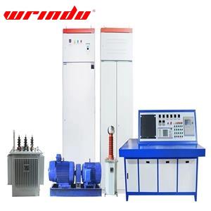
The system is also suitable for AC withstand voltage testing of transformers up to 120MVA/110kV, as well as 110kV busbars, GIS equipment, and switchyard systems. Its strong capacitive load capability ensures stable resonance performance and accurate insulation assessment, making it an ideal solution for commissioning tests, preventive maintenance, and acceptance testing in substations, power utilities, industrial facilities, and electrical engineering projects.
I. Working Environment
· Ambient Temperature: -15℃ – 40℃
· Relative Humidity: ≤90%RH
· Altitude: ≤3500m
II. Main Application Scope of the Device
1. Suitable for AC withstand voltage test of 300mm², 10kV cables with length up to 3km, capacitance ≤1.11μF, test frequency 30~300Hz, and test voltage U≤22kV.
2. Suitable for AC withstand voltage test of 300mm², 35kV cables with length up to 1km, capacitance ≤0.1945μF, test frequency 30~300Hz, and test voltage U≤52kV.
3. Suitable for AC withstand voltage test of 300mm², 110kV cables with length up to 0.2km, capacitance ≤0.0294μF, test frequency 30~300Hz, and test voltage U≤128kV.
4. Suitable for AC withstand voltage test of transformers below 120MVA/110kV, capacitance ≤0.02μF, test frequency 45~65Hz, and test voltage U≤160kV.
5. Suitable for AC withstand voltage test of 110kV busbars, GIS, and switch substation systems, test frequency 30~300Hz, and test voltage U≤265kV.
III. System Technical Specifications and Performance
3.1 System Technical Parameters
Parameter | Specification |
Rated Output Voltage | 0~270kV |
Resonant Voltage Waveform | Sine wave, waveform distortion rate <1.0% |
Maximum Test Object Current | 1A |
Maximum Test Capacity | 270kVA |
Output Frequency | 30~300Hz |
Operating Time | Continuous operation for 60min under full power output |
Quality Factor (Q Factor) | 30~90 |
Input Working Power Supply | Single-phase 220V or three-phase 380V±5%, 50Hz |
Ambient Temperature | -15℃~+40℃ |
Relative Humidity | <90RH%, no condensation |
Altitude | <3500m |
Noise | ≤50dB |
3.2 System Performance Features
1. Making full use of the company's advantages in electronic measurement technology and electromagnetic compatibility, the entire set of equipment is independently developed, designed and produced, including: variable frequency power supply, excitation transformer, cast-type high-voltage reactor and high-precision capacitive voltage divider.
2. Equipped with manual/automatic mode, large-screen display, test parameter setting, and automatic timing and operation prompt functions.
3. With multiple protection functions, such as overvoltage protection, overcurrent protection, discharge protection, detuning protection, etc.
IV. Device Capacity Determination
To meet the AC withstand voltage test of 300mm², 110kV cables with length 0.2km, capacitance ≤0.0294μF, test frequency 30~300Hz, and test voltage U≤128kV:
· Selected frequency: 75Hz
· Test current I=2πfCU_test =2π×75×0.0294×10⁻⁶×128×10³=1.8A
· Corresponding reactor inductance L=1/ω²C=150H
Design six sections of reactors, which are used in a combination of three in series and two groups in parallel. The parameters of a single reactor are 45kVA/45kV/1A/100H, and the total capacity of the device is 270kVA.
Verification:
1.To meet the AC withstand voltage test of transformers below 120MVA/110kV, capacitance ≤0.02μF, test frequency 45~65Hz, test voltage U≤160kV:
o Use four reactors in series, inductance L=100×4=400H
o Test frequency f=1/(2π√(LC))=1/(2×3.14×√(400×0.02×10⁻⁶))=56.3Hz
o Test current I=2πfCU_test =2π×56.3×0.02×10⁻⁶×160×10³=1A
2.To meet the AC withstand voltage test of 300mm², 35kV cables with length 1km, capacitance ≤0.1945μF, test frequency 30~300Hz, test voltage U≤52kV:
o Use two reactors in series and three groups in parallel, inductance L=100×2/3=66.7H
o Test frequency f=1/(2π√(LC))=1/(2×3.14×√(66.7×0.1945×10⁻⁶))=44.7Hz
o Test current I=2πfCU_test =2π×44.7×0.1945×10⁻⁶×52×10³=2.8A
3.To meet the AC withstand voltage test of 300mm², 10kV cables with length 3km, capacitance ≤1.11μF, test frequency 30~300Hz, test voltage U≤22kV:
o Use six reactors in parallel, inductance L=100/6=22H
o Test frequency f=1/(2π√(LC))=1/(2×3.14×√(22×1.126×10⁻⁶))=37Hz
o Test current I=2πfCU_test =2π×37×1.11×10⁻⁶×22×10³=5.7A
Conclusion: The device capacity is set to 270kVA/270kV, divided into six reactors. A single reactor is 45kVA/45kV/1A/100H. The combination of reactors can meet the test requirements of the above test objects.
V. Equipment Combination Table for Testing
Test Object | Length Range | Reactor Combination (6 units of 45kVA/45kV) | Excitation Transformer Output Terminal Selection |
10kV/300mm² cable (test voltage 22kV, test time 5min) | Below 500m | 1 reactor unit | 1.2kV |
| 500~1000m | 2 reactors in parallel | 1.2kV |
| 1000~1500m | 3 reactors in parallel | 1.2kV |
| 1500~2000m | 4 reactors in parallel | 1.2kV |
| 2000~2500m | 5 reactors in parallel | 1.2kV |
| 2500~3000m | 6 reactors in parallel | 1.2kV |
35kV/300mm² cable (test voltage 52kV, test time 60min) | Below 330m | 2 reactors in series | 2.5kV |
| 330~660m | 2 groups of 2 reactors in series (parallel connection) | 2.5kV |
| 660~1000m | 3 groups of 2 reactors in series (parallel connection) | 2.5kV |
110kV/300mm² cable (test voltage 128kV, test time 60min) | 200m | 2 groups of 3 reactors in series (parallel connection) | 5kV |
Transformers below 120MVA/110kV (test voltage 160kV, test time 1min) | - | 4 reactors in series | 5kV |
110kV substation system (test voltage 265kV, test time 1min) | - | 6 reactors in series | 15kV |
VI. Technical Specifications and Performance of Main Components
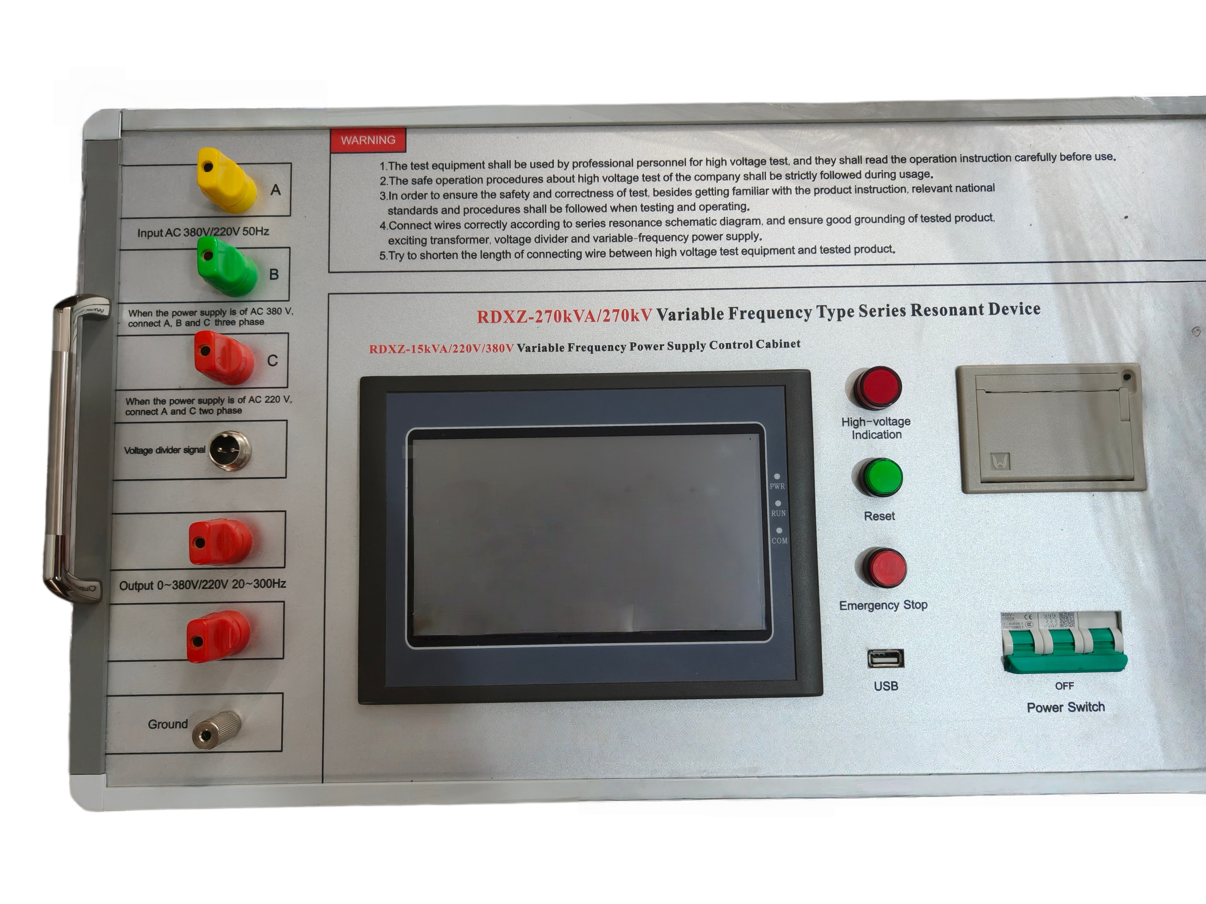
6.1 Variable Frequency Power Supply Control Cabinet (Model: RDXZ-15kVA/220V/380V) - 1 Unit
6.1.1 Technical Parameters
Parameter | Specification |
Input Working Power Supply | Single-phase 220V or three-phase 380V±5%, 50Hz |
Output Voltage and Current | 0~400V, maximum current 37.5A |
Output Frequency | 30~300Hz, frequency adjustment fineness 0.1Hz, instability <0.05% |
Rated Output Capacity | 15kVA |
Overall Dimensions and Weight | 360×340×320mm; 25kg |
6.1.2 Performance Features
1. Parameter setting: Can set or select parameters such as test voltage, withstand voltage time, test mode, test current, etc.
2. Test modes: Manual test mode, automatic test modea. Manual test mode: Equipped with functions such as voltage boosting, tuning (manual and automatic), voltage reduction (manual and automatic), etc.b. Automatic test mode: After entering the test state, automatically perform tuning, voltage boosting, timing, voltage reduction, cut off the main circuit and switch to the test result interface.
3. Protection functions and information prompts: With multiple protection functions such as high-voltage overvoltage protection, low-voltage overcurrent protection, detuning protection, zero-position protection, discharge protection, etc.
4. Data storage function: Save and review test results, etc.a. Test results: After manual or automatic test, the detailed test parameters can be displayed on the test result interface, and the parameters can be saved in the memory. The memory is a non-volatile memory that can store 200 test records.b. Data query: The saved test result data can be displayed on the screen
5. Automatic voltage stabilization function: The system automatically tracks and maintains a stable test voltage according to the set test voltage or manual voltage boosting result, with a voltage stability of up to 1%.
6. Frequency modulation range setting: The frequency modulation range can be set to 20~300Hz.
7.Overvoltage protection function: Software overvoltage protection value, rich high-voltage overvoltage protection functions, more secure, effectively protecting the safety of personnel, equipment and test objects.
8.Overcurrent protection: The overcurrent protection value can be manually set; when the output current of the entire set of equipment reaches the protection setting value, the entire set of equipment is automatically cut off.
9.Breakdown protection: With discharge or flashover protection function. When a ground flashover occurs on the high-voltage side, the entire set of equipment is automatically cut off. It will not cause harm to test equipment and personnel, and the electronic components in the variable frequency power supply will not be broken down.
10.Power failure protection: The device can quickly protect after the test power supply is cut off.
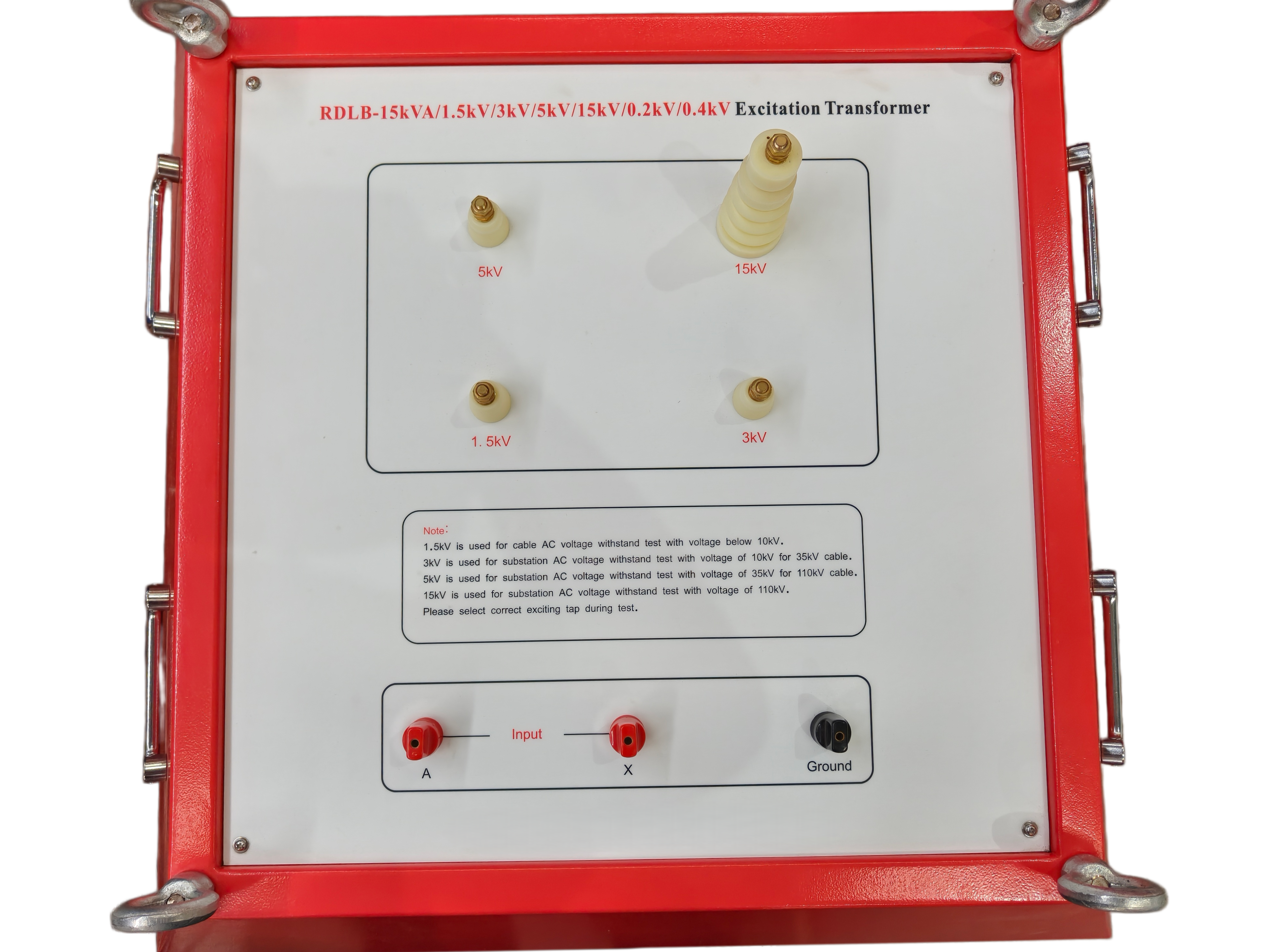
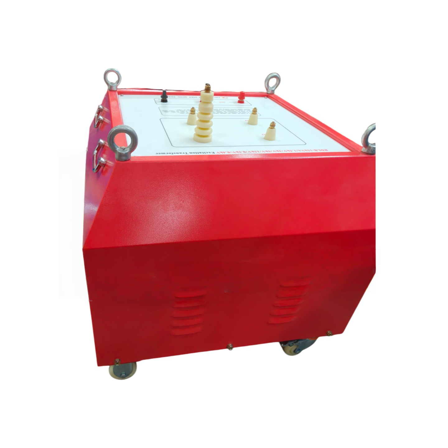
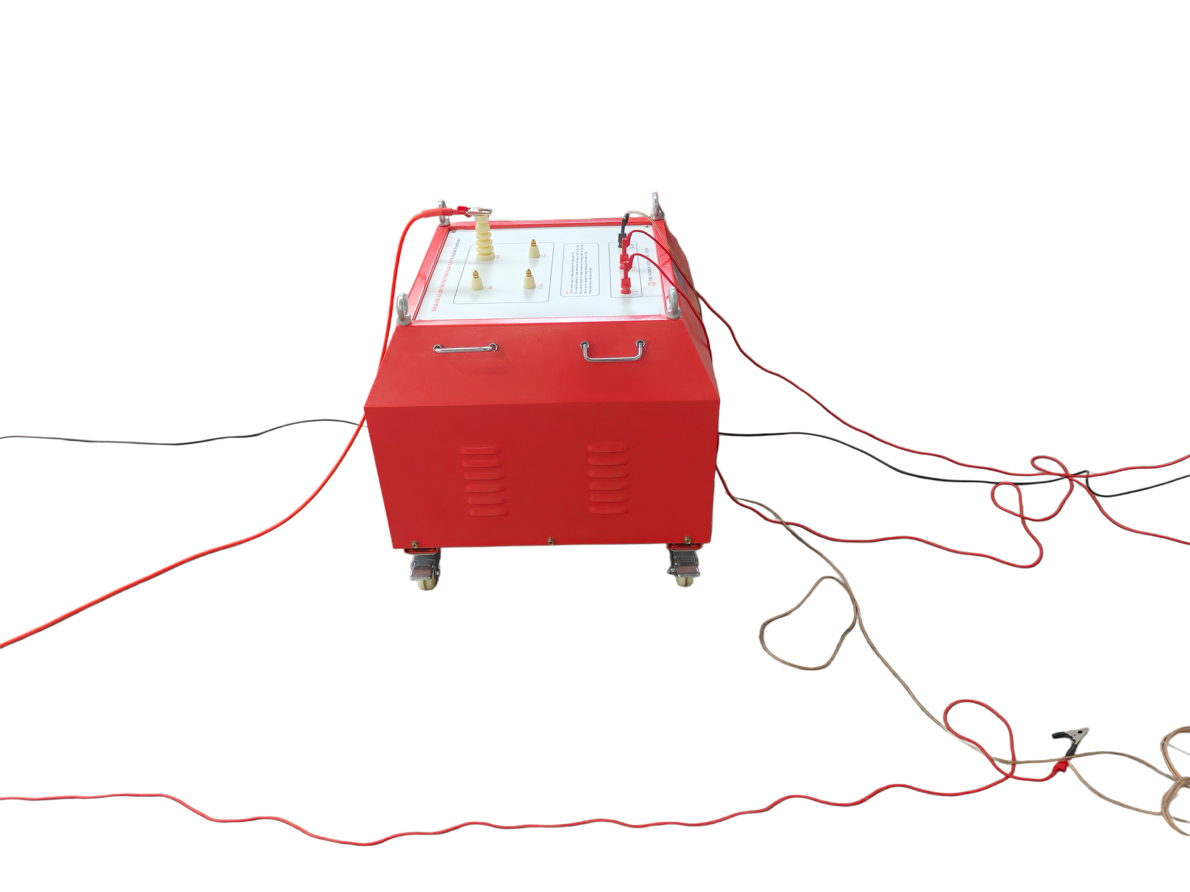
6.2 Excitation Transformer (Model: RDLB-15kVA/1.2kV/2.5kV/5kV/15kV/0.4kV) - 1 Unit
Configuration feature: Separate processing of test objects with high voltage, small current, short time and low voltage, large current, long time. Configure different tap excitation transformers to ensure the maximum utilization rate and lightest weight of the excitation transformer.
6.2.1 Technical Parameters
Parameter | Specification |
Rated Capacity | 15kVA |
Input Voltage | 0~400V |
Output Voltage | 1.2kV; 2.5kV; 5kV; 15kV |
Operating Frequency Range | 30~300Hz |
Operating Time | 60min |
Overall Dimensions and Weight | 360×280×360mm; 75kg |
Application Scope | Electrical main equipment test and cable test |
6.2.2 Performance Features
1.The excitation transformer adopts a dry-type structure, no oil leakage.
2. Electrostatic shielding layers are provided between the high and low voltage windings and the iron core, which is both an excitation transformer and an isolation transformer.
3. Built-in overvoltage protection to prevent breakdown and counterattack.
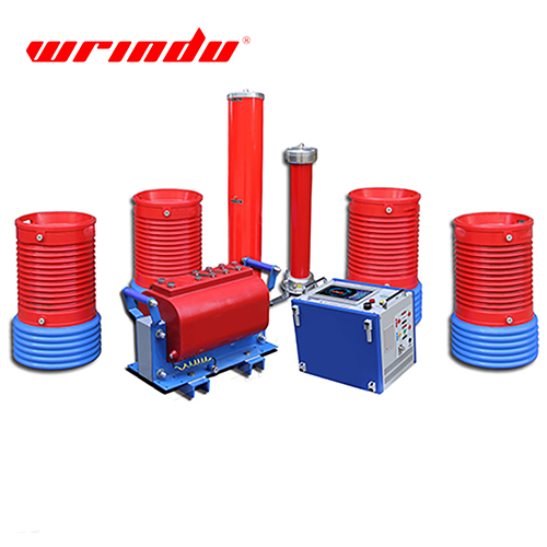
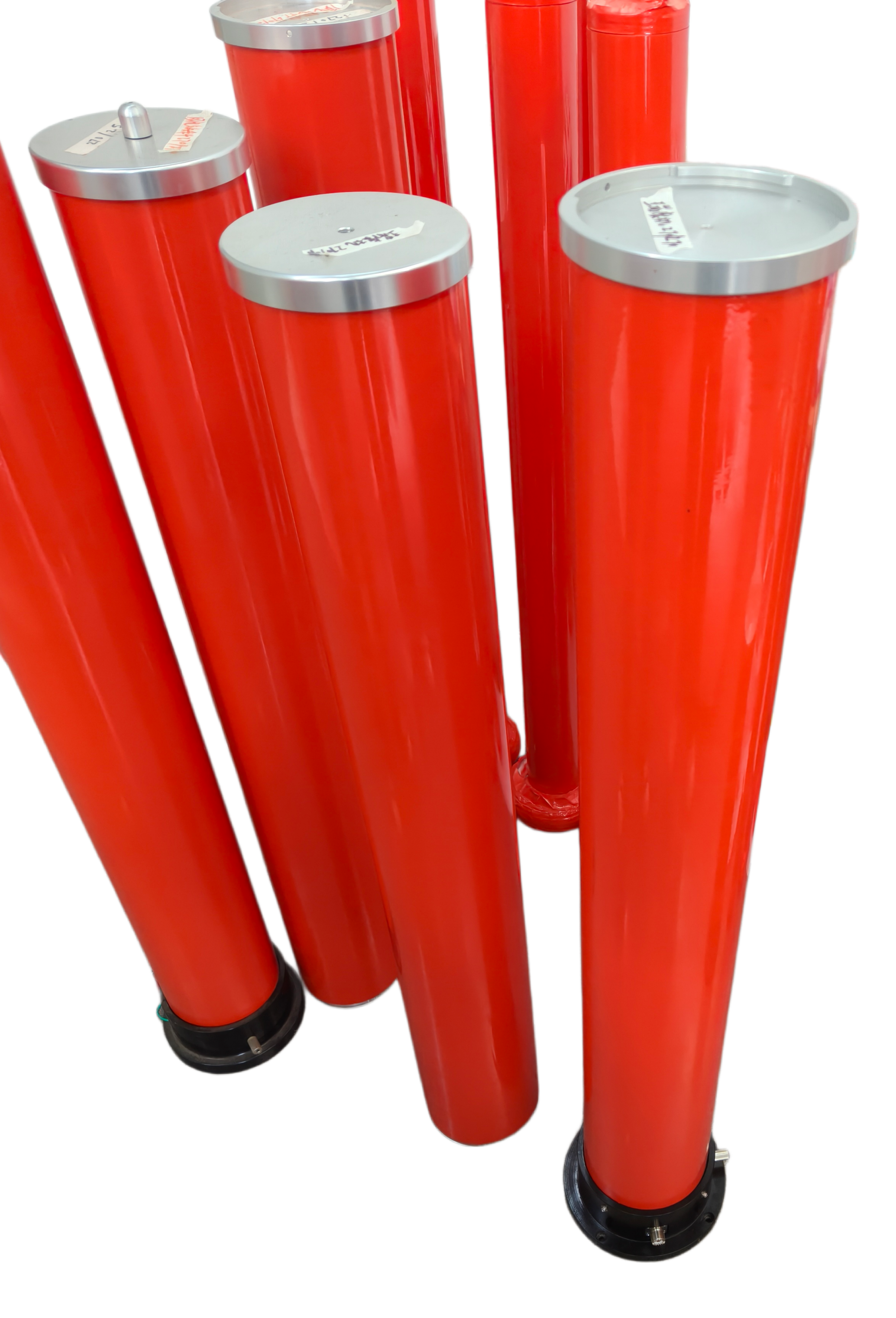
6.3 High-Voltage Resonant Reactor (Model: DK-45kVA/45kV) - 6 Units
6.3.1 Technical Parameters
Parameter | Specification |
Rated Maximum Working Voltage | 45kV (effective value) |
Rated Maximum Working Current | 1A (effective value) |
Rated Capacity | 45kVA |
Rated Inductance | 100H |
Operating Frequency | 30~300Hz |
Operating Time | 60min |
Overall Dimensions and Weight | φ300×350mm; 45kg/unit |
6.3.2 Performance Features
1.The high-voltage resonant reactor is integrally cast with vacuum epoxy resin, with a hydrophobic layer on the outside, good moisture resistance, insulation heat resistance class F, meeting the national standards for dry-type reactors.
2.The reactor is portable, small in size and light in weight.
3.The reactor is equipped with an eddy current-proof insulating base. When connected in series, it can be stacked in groups to reduce the overall height, reduce labor intensity, and enhance safety and stability.
6.4 (Model: RDFC-270kV/500pF) - 1 Unit
6.4.1 Technical Parameters
Parameter | Specification |
Working Mode | Pure capacitive type |
Rated Voltage | 270kV effective value |
Rated Capacitance | 500pF |
Operating Frequency | 30~300Hz |
Measurement Error | <1.5% |
Overall Dimensions and Weight | φ120×1000mm; 8kg (2 sections) |
6.4.2 Performance Features
1. Can operate continuously for 1 hour under rated voltage.
2. Within the range of 30~300Hz, its accuracy and stability remain unchanged as required.
3. Dielectric loss value at 20℃ and 0.4~0.5UN: ≤0.15
4. Voltage division ratio error: ≤1.5% for effective value
5. The capacitors of the high and low voltage arms adopt the same dielectric structure, with small temperature coefficient and small angular displacement, and the voltage division ratio remains unchanged within 30~300Hz.
6. Voltage measurement is led to the variable frequency power supply through special test leads for measurement.
VII. Basic Configuration of the System
(I) List of Main Components
Serial Number | Equipment Name | Specification | Unit | Quantity | Remarks |
1 | Variable Frequency Power Supply Control Cabinet | RDXZ-15kVA/220V/380V | Unit | 1 | 15kVA, 30~300Hz |
2 | Excitation Transformer | RDLB-15kVA/1.2kV/2.5kV/5kV/15kV/0.4kV | Unit | 1 | 15kVA, 30~300Hz, 60minOutput voltage: 1.2kV; 2.5kV; 5kV; 15kV |
3 | High-Voltage Resonant Reactor | RDDK-45kVA/45kV | Unit | 6 | 45kV, 1A, 100H, 60min |
4 | Capacitive Voltage Divider | RDFC-270kV/500pF | Unit | 1 | 270kV, 500pF, accuracy class 1.5, pure AC |
(II) List of Equipment Accessories and Related Documents
Serial Number | Name | Model and Specification | Unit | Quantity | Remarks |
1 | Rainproof and Dustproof Cover | Matching the equipment size | Piece | 7 | - |
2 | Test Wire | Configured according to the complete set of equipment requirements | Package | 1 | - |
3 | Factory Test Report | - | Copy | 1 | - |
4 | Complete Set of Equipment Operation Manual | - | Copy | 1 | - |
5 | Product Qualification Certificate | - | Copy | 1 | - |
6 | Packing List | - | Copy | 1 | - |