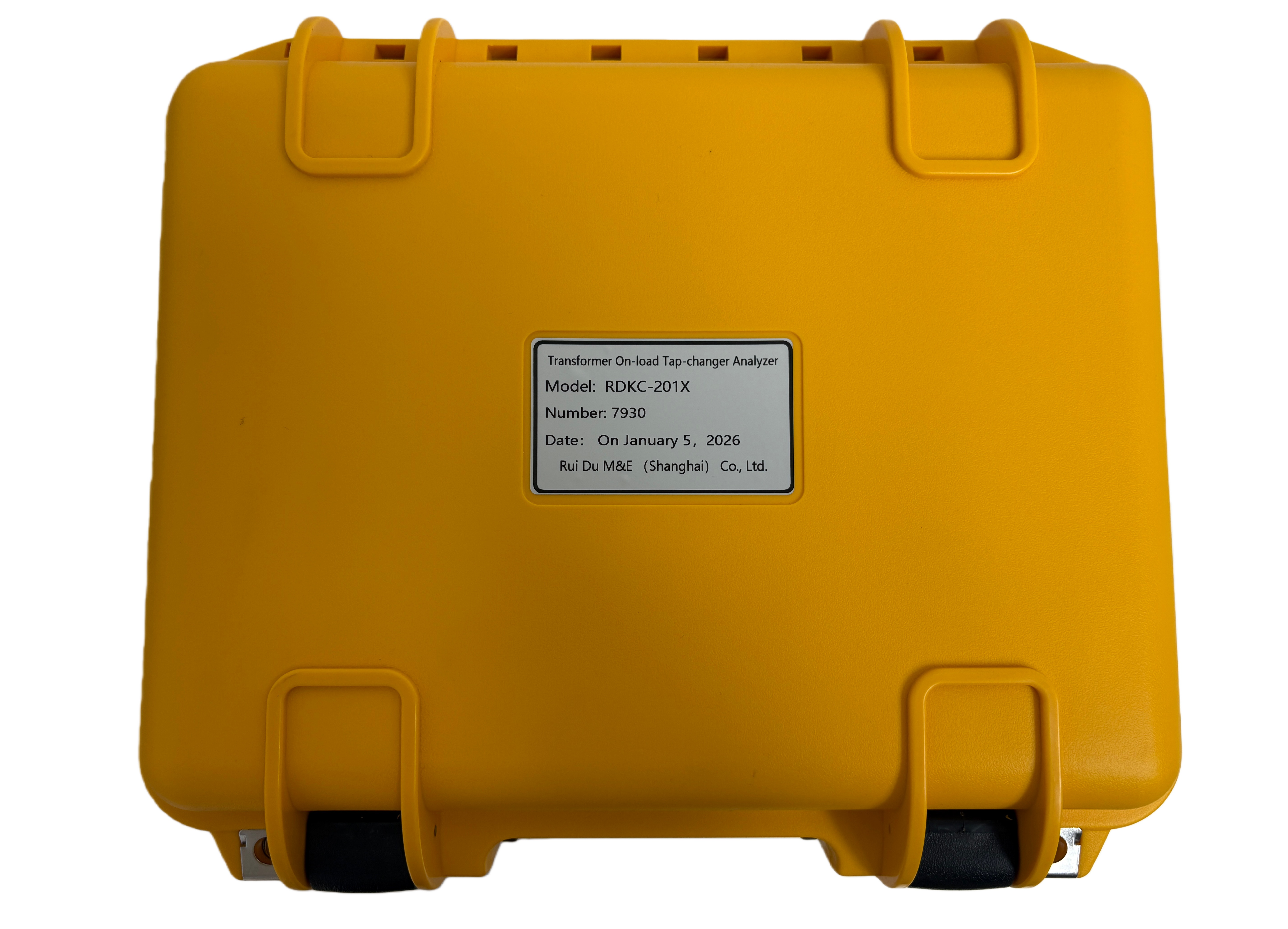
Transformer On-load Tap-changer Analyzer

- Wrindu
- Shanghai, China
- about 10 working days
- 1000 set/month
- RDKC-201X
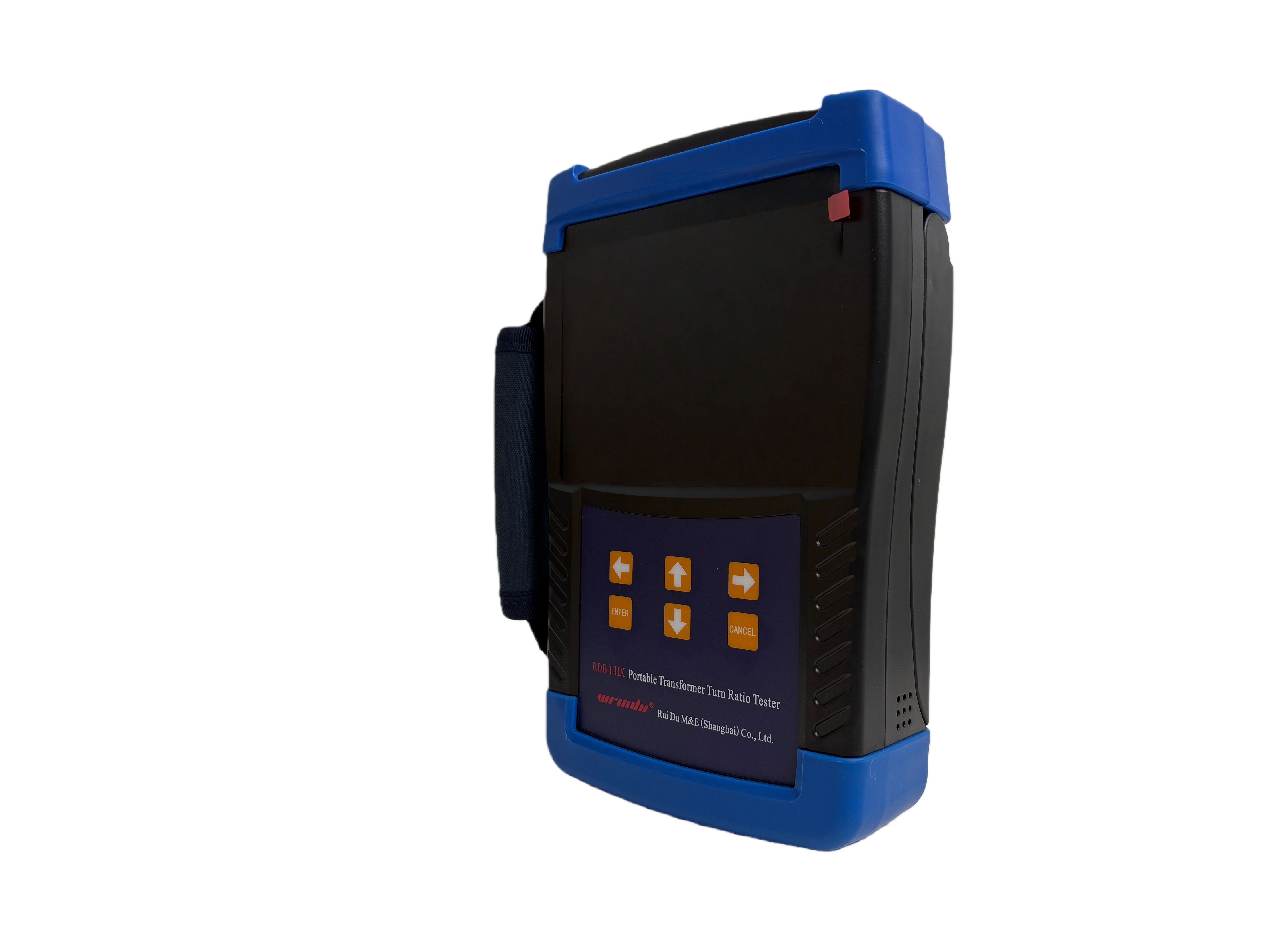
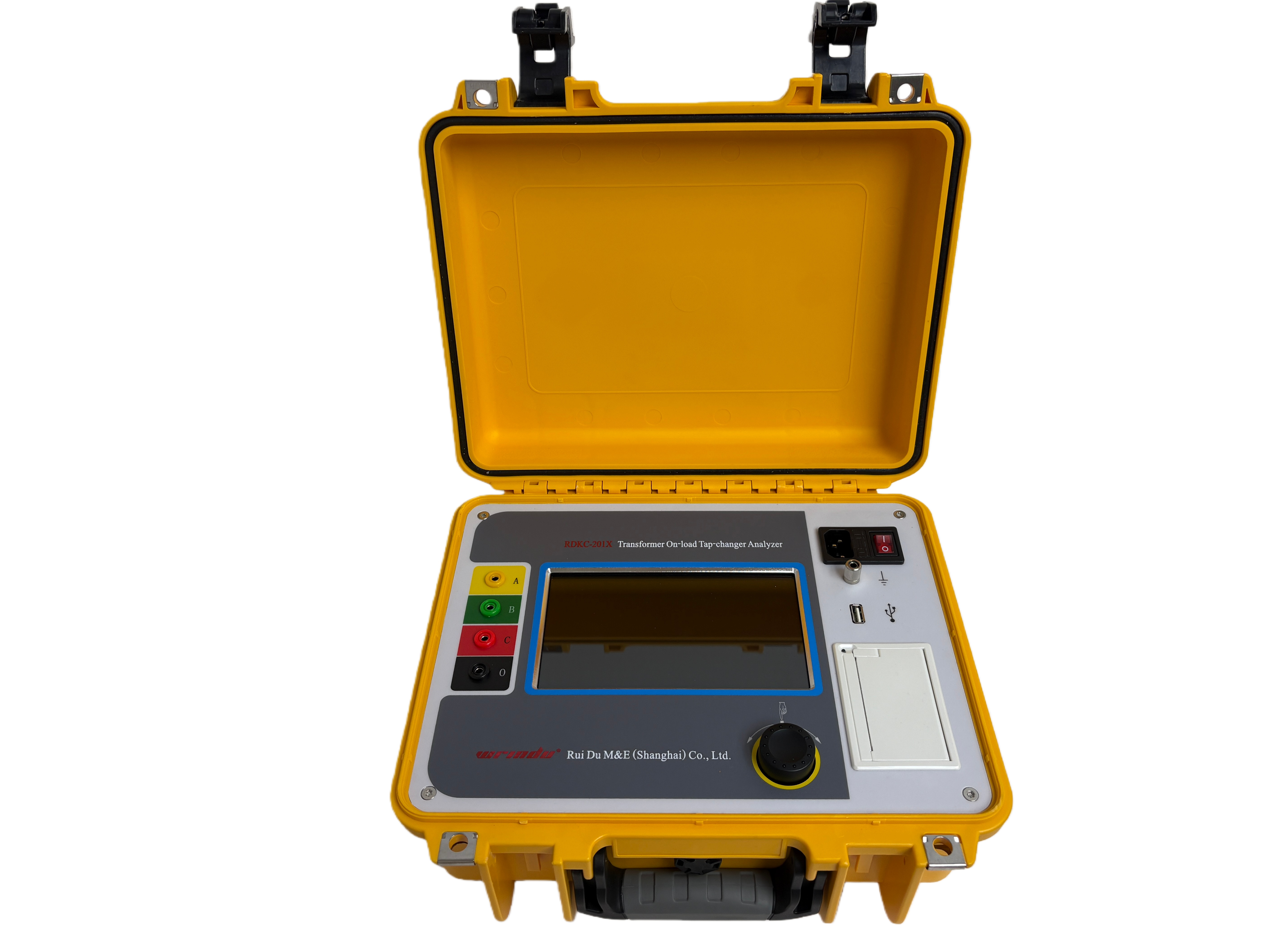
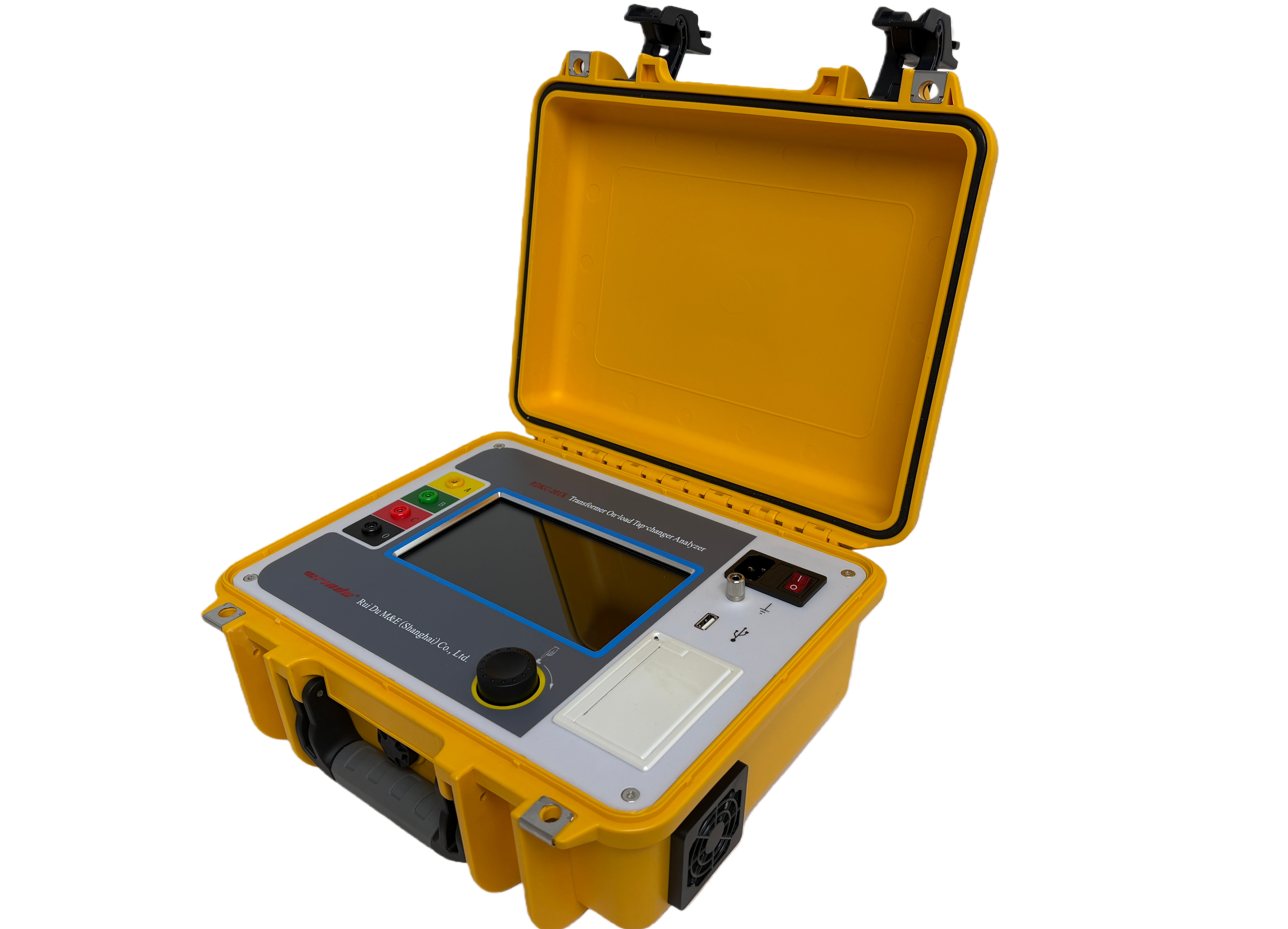
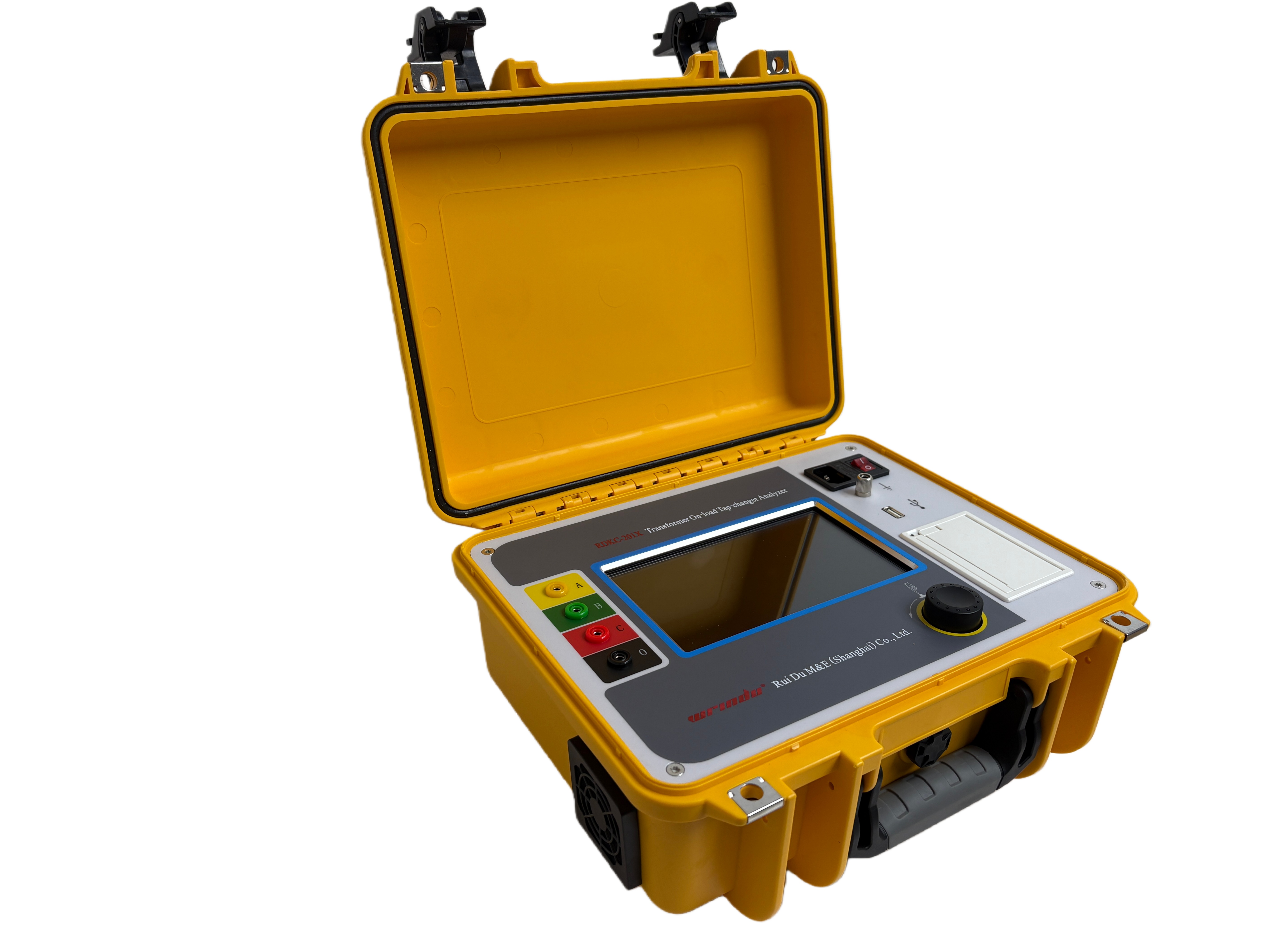
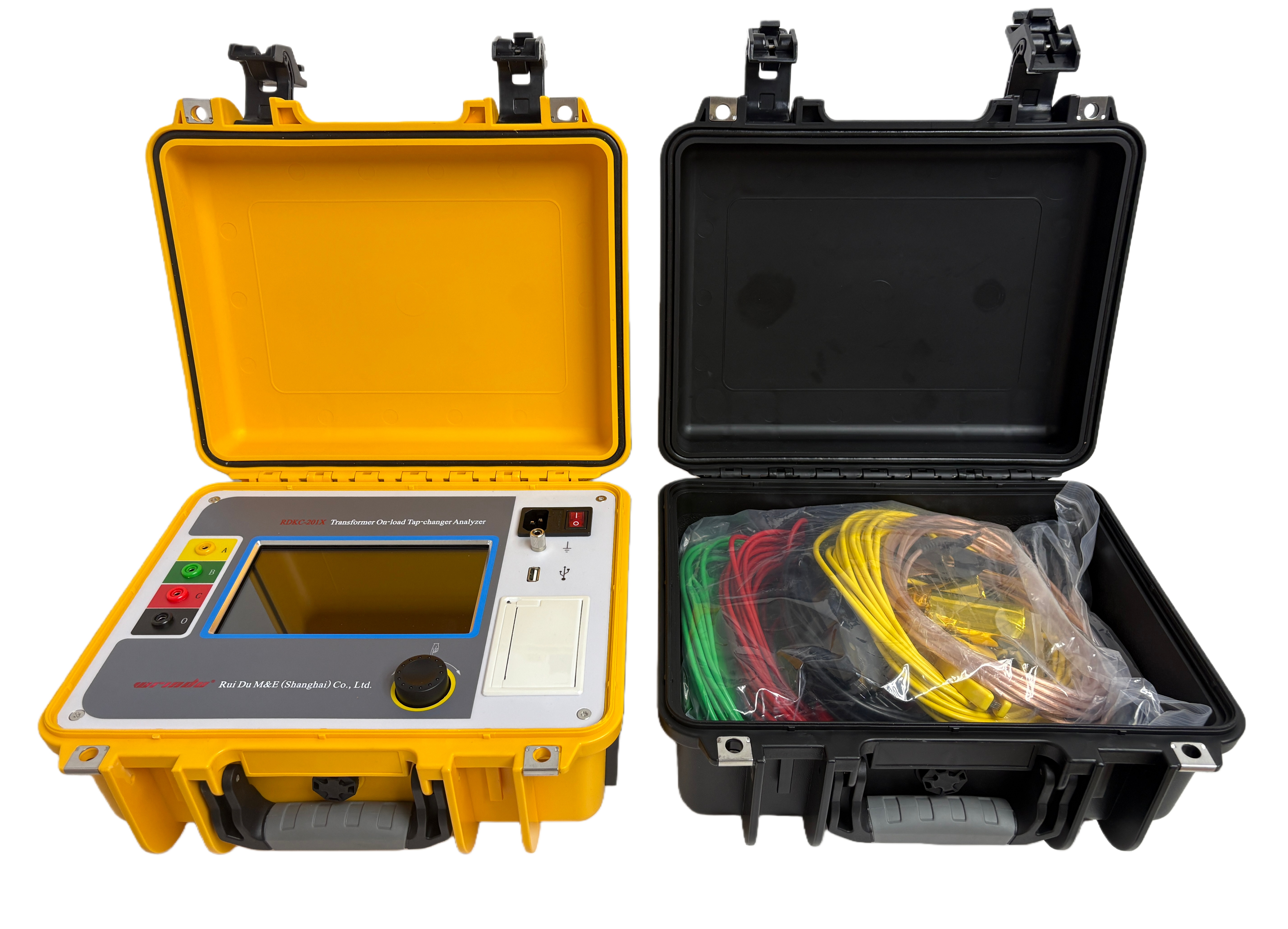
The RDKC-201X Transformer On-Load Tap-Changer Analyzer accurately measures key OLTC parameters, including transition waveform, transition time, instantaneous transition resistance, and three-phase synchronicity.
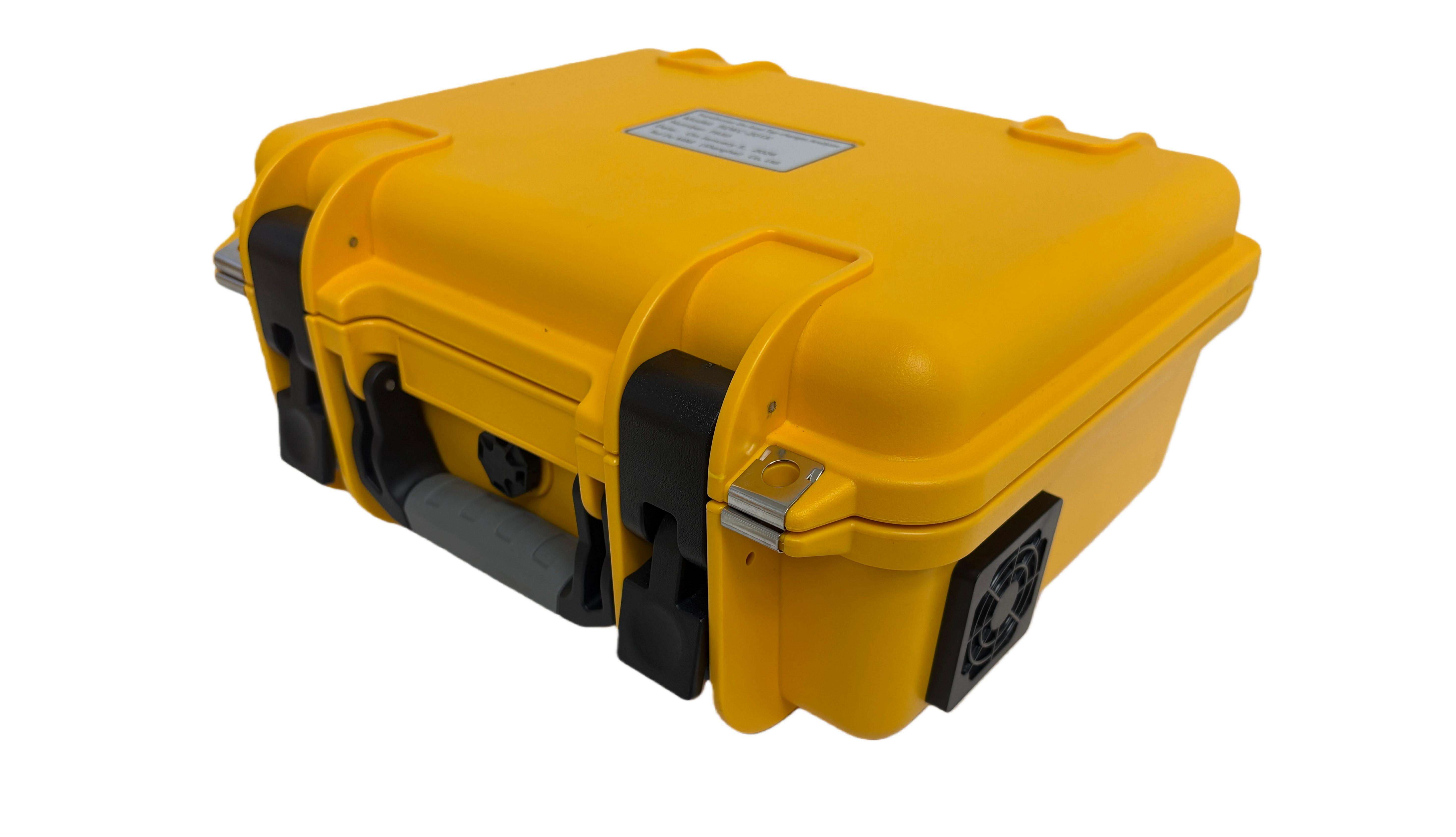
Its intelligent design, compact size, and lightweight build make it ideal for power supply units and transformer manufacturers to ensure safe operation and improve product quality.
Product Features
1. The tester has a large output current, which can be adapted to test requirements with smaller transition resistance values.
2. The tester is equipped with three current output gears, which can meet the testing scenarios of different types of samples.
3. The tester is equipped with a complete protection circuit, ensuring strong product reliability.
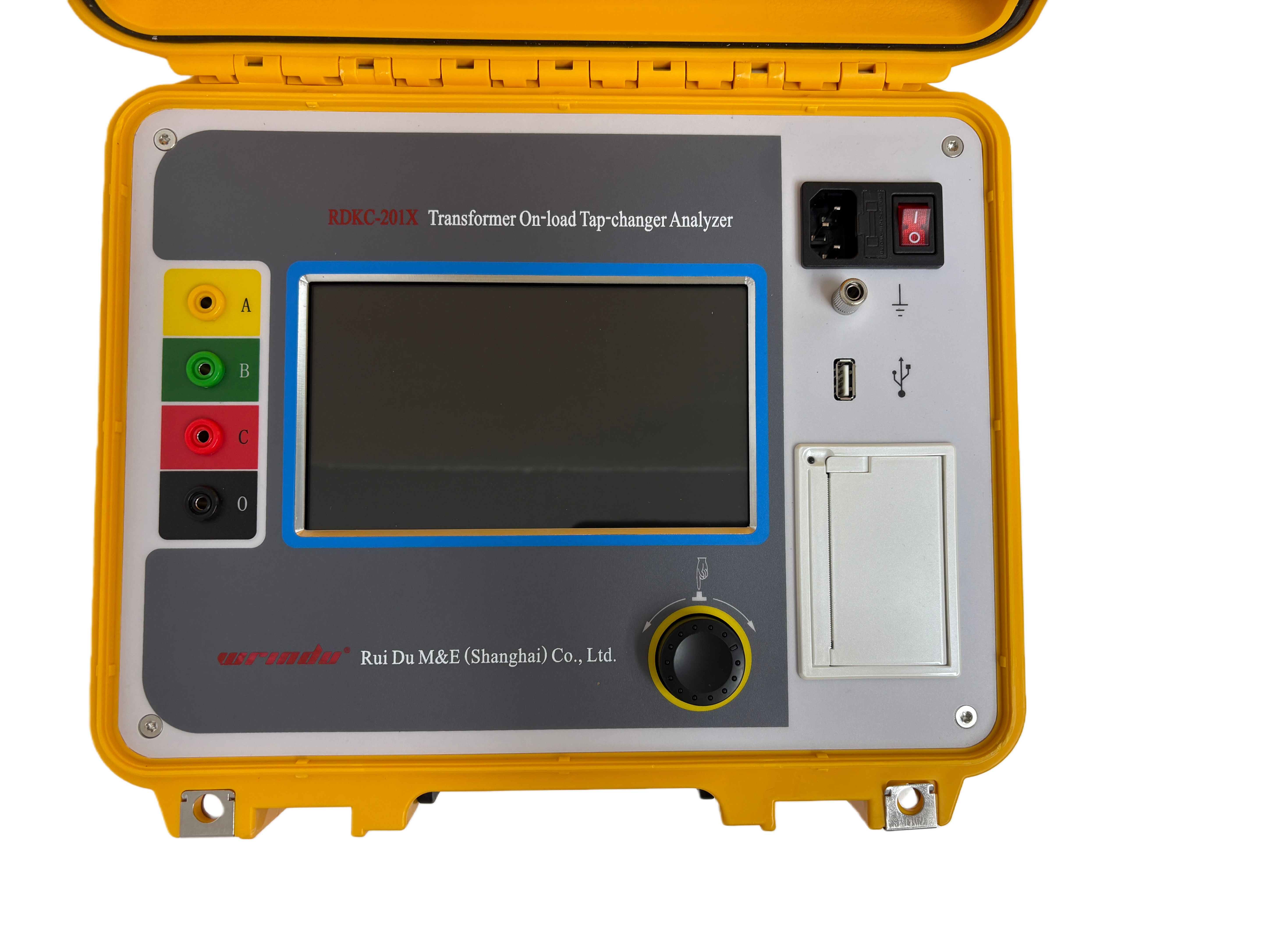
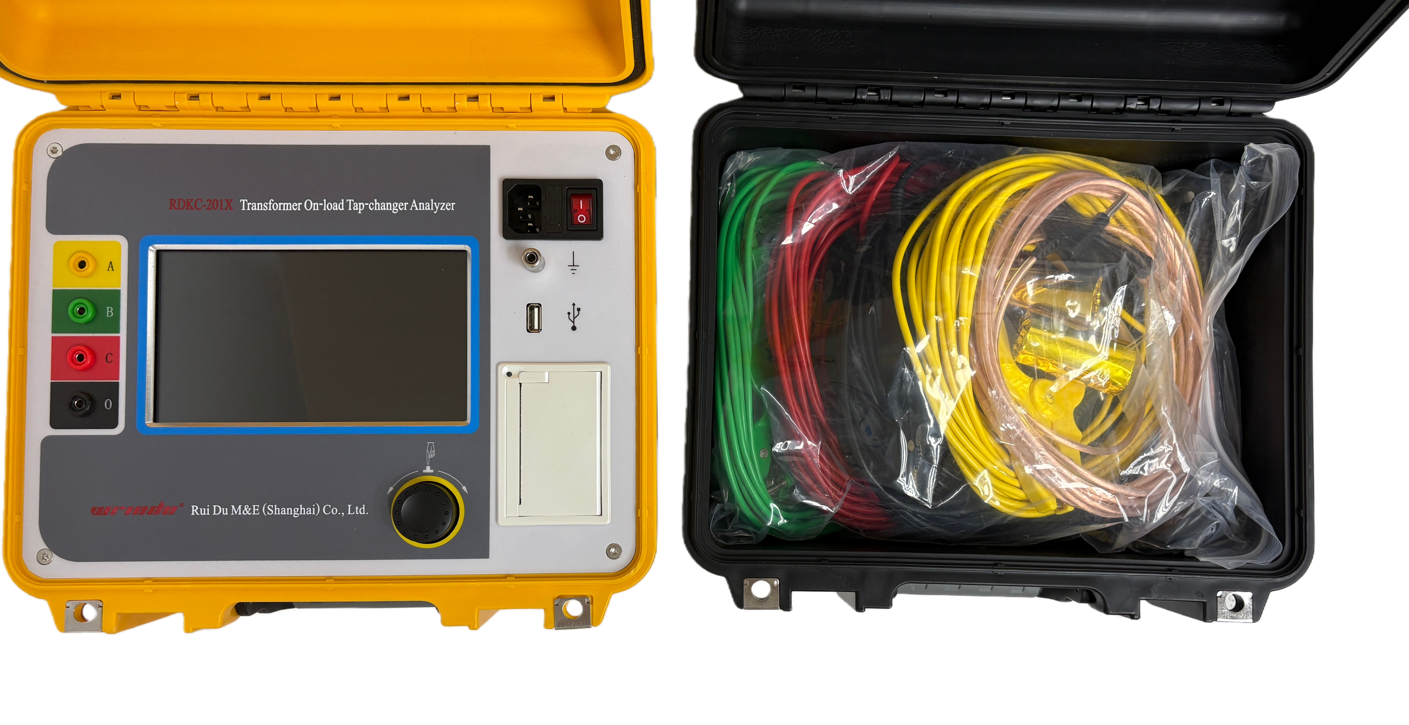
4.The tester is equipped with a 7-inch full touch industrial grade color LCD screen, with a resolution of 1024×600, full view display, and a brightness of up to 400cd/m². It can display clearly outdoors; The touch panel adopts explosion-proof glass, suitable for industrial environments.
5. The tester supports both rotating mouse operation and touch operation, and is equipped with a brand new UI display system, providing users with a safe and convenient dual operation guarantee.
6. The tester is equipped with a thermal printer to facilitate on-site printing of test data.
7. The tester has both local storage and U-disk storage functions, and can be used in conjunction with PC software to make waveform analysis more efficient and convenient.
For more information about Transformer Testing Equipment, click the transformer testing list.
Product Specifications and Technical Parameters
Item | Description |
Test current output | 1A, 0.5A, 0.3A |
Transition resistance | Range: 0.5 ~ 20Ω @1A , 2.0 ~ 40Ω @0.5A , 5.0 ~ 60Ω @0.3A; Accuracy: ±(5%rdg+0.1Ω); Resolution: 0.01Ω |
Transition time | Range: 0.1 ~ 300ms; Accuracy: ±1ms; Resolution: 0.1ms |
Display | 7-inch full touch industrial grade color LCD screen, resolution 1024×600 |
Port | USB |
Operation method | Rotating mouse/Touch operation |
Power supply | AC 220V±10%, 50Hz/60Hz. |
Operating conditions | Temperature -10 ~ 50℃; Relative humidity ≤90%, no condensation. |
FAQs
Q1: What can the Transformer On-load Tap-changer Analyzer measure?
A: It accurately measures OLTC transition waveform, transition time, instantaneous transition resistance, and three-phase synchronicity. The device supports currents of 1A, 0.5A, and 0.3A, and can test transition resistances from 0.5 Ω to 60 Ω with high resolution, making it suitable for various transformer types.
Q2: How reliable is this OLTC analyzer for field and industrial use?
A: The analyzer is highly reliable thanks to its complete protection circuits, explosion-proof touch panel, and industrial-grade design. It operates safely in temperatures from -10 °C to 50 °C and up to 90% relative humidity without condensation.
Q3: What makes the RDKC-201X analyzer user-friendly?
A: Its 7-inch full touch industrial LCD screen (1024×600, 400 cd/m² brightness) clearly displays waveforms even outdoors. Users can operate it via touch or rotating mouse, with a modern UI for convenient and safe testing.
Q4: Can the OLTC analyzer store and print test results?
A: Yes, it includes both local and U-disk storage, supports PC software for waveform analysis, and comes with a thermal printer for immediate on-site printouts.
Q5: Does the analyzer handle different transformer testing scenarios?
A: Absolutely. With three current output gears and a wide transition resistance range, the analyzer adapts to different transformer types and testing conditions while maintaining ±(5% rdg + 0.1 Ω) accuracy for resistance and ±1 ms for transition time.
Q6: What are the power and connection requirements for the analyzer?
A: It runs on AC 220 V ±10%, 50/60 Hz, and includes a USB port for data transfer and PC integration, ensuring flexible and convenient operation in substations or factory environments.
What Is the RDKC-201X Transformer On-load Tap-changer Analyzer?
The RDKC-201X Transformer On-load Tap-changer Analyzer is designed to check the switching performance of a transformer's on-load tap changer (OLTC). It measures transition time, transition resistance, and transition waveforms to help maintenance teams identify possible switching problems.
An OLTC changes a transformer's tap position while the transformer remains in service. During switching, the transition process must follow the required sequence to maintain reliable operation. Abnormal transition time or resistance may indicate contact wear, poor connections, or other mechanical or electrical problems that require further inspection.
The RDKC-201X provides three test current options: 1 A, 0.5 A, and 0.3 A. Its measurement range depends on the selected current, allowing users to choose a suitable setting for different test samples.
Key Applications of the RDKC-201X
The RDKC-201X can support OLTC testing during transformer maintenance, troubleshooting, and performance checks.
1. Routine transformer maintenance: Check OLTC transition time and resistance to help assess switching performance.
2. Fault investigation: Compare measured waveforms and resistance values with previous test records to identify unusual changes.
3. Transformer repair and inspection: Check the switching characteristics of an OLTC after maintenance or repair.
4. Factory testing: Support the inspection of transformer tap-changing mechanisms during manufacturing and quality checks.
5. Three-phase comparison: Review phase-related test results to help identify differences in switching behavior.
The test results should be assessed together with the transformer's technical documents, manufacturer requirements, and previous measurement records.
How Does OLTC Transition Resistance Testing Work?
Transition resistance testing evaluates the resistance in the OLTC switching path during the transition between tap positions. The transition process helps control the current while the tap changer moves from one position to another.
Resistance measurements can help identify possible problems such as worn contacts, poor electrical connections, or abnormal contact conditions. However, a resistance reading alone cannot confirm the exact cause of a fault.
The RDKC-201X offers three current settings with different resistance measurement ranges:
| Test Current | Transition Resistance Range |
|---|---|
| 1 A | 0.5–20 Ω |
| 0.5 A | 2–40 Ω |
| 0.3 A | 5–60 Ω |
The specified resistance accuracy is ±(5% of reading + 0.1 Ω), with a resolution of 0.01 Ω.
Users should select a current setting that covers the expected resistance value. The test current and resistance range must be suitable for the OLTC under test.
How to Select the Test Current?
Selecting the correct test current helps ensure that the expected resistance falls within the instrument's measurement range.
| Test Current | Resistance Range | Selection Guidance |
|---|---|---|
| 1 A | 0.5–20 Ω | Use when the expected resistance falls within this range and the test requirements permit 1 A. |
| 0.5 A | 2–40 Ω | Use when the expected resistance is within this range and a lower current is appropriate. |
| 0.3 A | 5–60 Ω | Use for higher resistance values within the specified range, when permitted by the test procedure. |
The available ranges overlap. Therefore, users should follow the OLTC manufacturer's instructions and the approved test procedure rather than choosing a current based only on the resistance value.
Before testing, confirm that the instrument settings, test connections, and test method are suitable for the equipment.
Recommended OLTC Testing Procedure
Follow the approved site procedure and the OLTC manufacturer's instructions when using the RDKC-201X.
1. Prepare the equipment. Check the analyzer, test leads, connectors, and power supply for visible damage.
2. Make the transformer safe. Isolate the transformer and follow the required lockout, grounding, and electrical safety procedures. Do not connect the analyzer to energized equipment unless the instrument's documented test method specifically permits it.
3. Connect the test leads. Follow the wiring diagram and connection instructions supplied with the analyzer.
4. Select the test current. Choose 1 A, 0.5 A, or 0.3 A according to the expected resistance and the approved test procedure.
5. Perform the measurement. Operate the analyzer according to its user manual and record the transition waveform, resistance, and time.
6. Repeat the test as required. Keep the test conditions consistent when comparing different phases, tap positions, or switching operations.
7. Review and save the results. Use the local storage or USB drive to retain test records. Print the results on site when a paper record is required.
8. Evaluate the data. Compare the measurements with manufacturer specifications and historical records. Investigate unusual results before making maintenance decisions.
Only qualified personnel should perform transformer testing. The test connections and operating sequence must follow the instrument manual and the site's electrical safety requirements.
How to Evaluate OLTC Test Results?
A useful OLTC test record should include the measured values and enough information to support a meaningful comparison.
| Test Item | What to Check | Why It Matters |
|---|---|---|
| Transition resistance | Compare readings with the manufacturer's limits and previous results. | Helps identify possible changes in the switching path. |
| Transition time | Check against the specified switching time. | Helps assess the timing of the switching process. |
| Transition waveform | Review unusual changes or unexpected patterns. | Helps identify behavior that needs further investigation. |
| Phase comparison | Compare equivalent measurements under consistent conditions. | Helps reveal possible differences between phases. |
| Historical records | Compare results from different maintenance periods. | Helps track changes and support maintenance planning. |
No single measurement should be used to diagnose every OLTC fault. Engineers should consider the OLTC design, test connections, operating conditions, waveform characteristics, and other inspection findings before deciding whether maintenance is necessary.
Technical Support and After-sales Service
Wrindu can provide product information and technical guidance to help customers understand the RDKC-201X's specifications, prepare for testing, and use the analyzer according to its operating instructions.
Before purchasing, customers can confirm the following details with the Wrindu team:
Whether the analyzer's resistance and transition time ranges match the intended OLTC application.
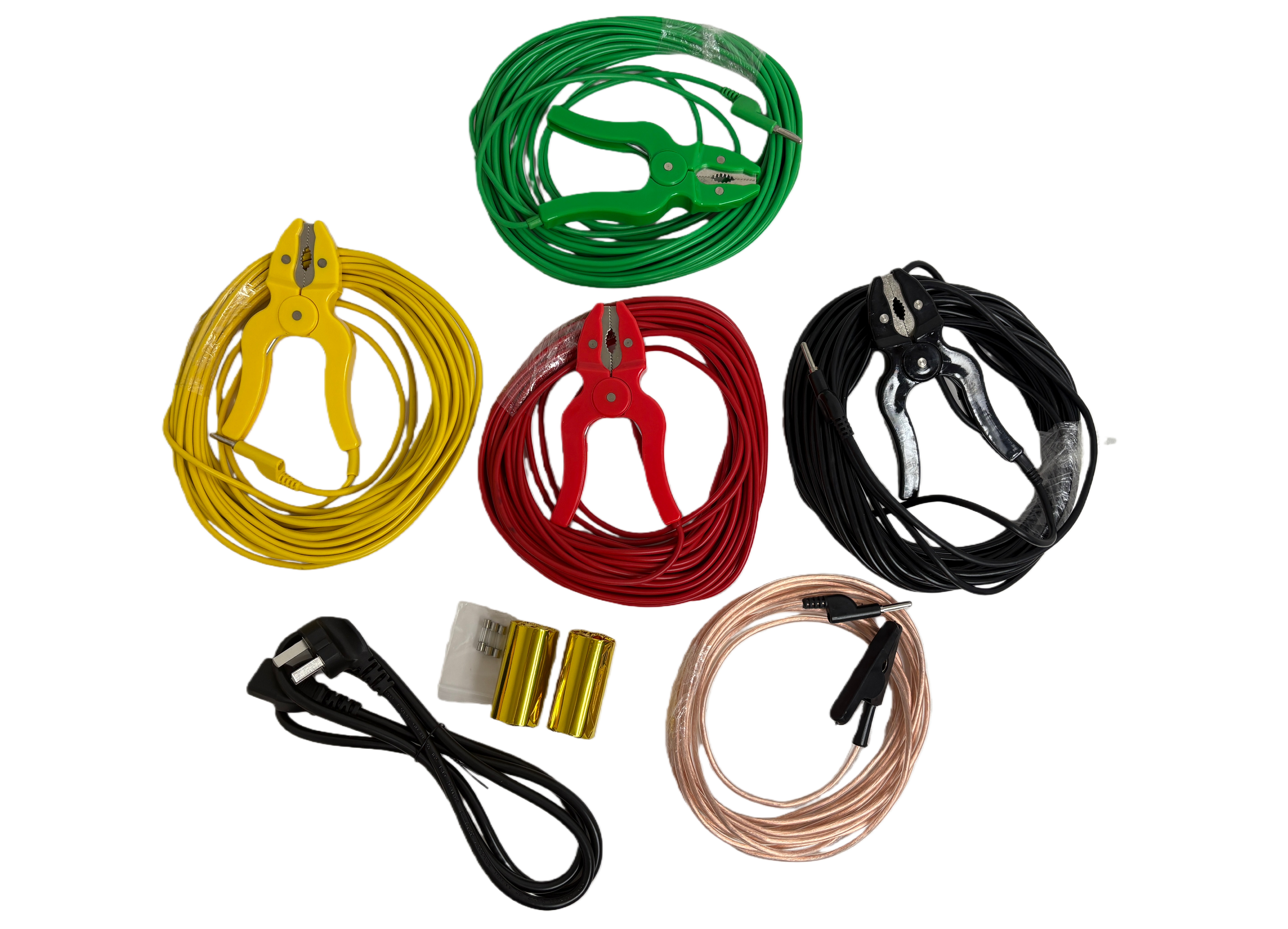
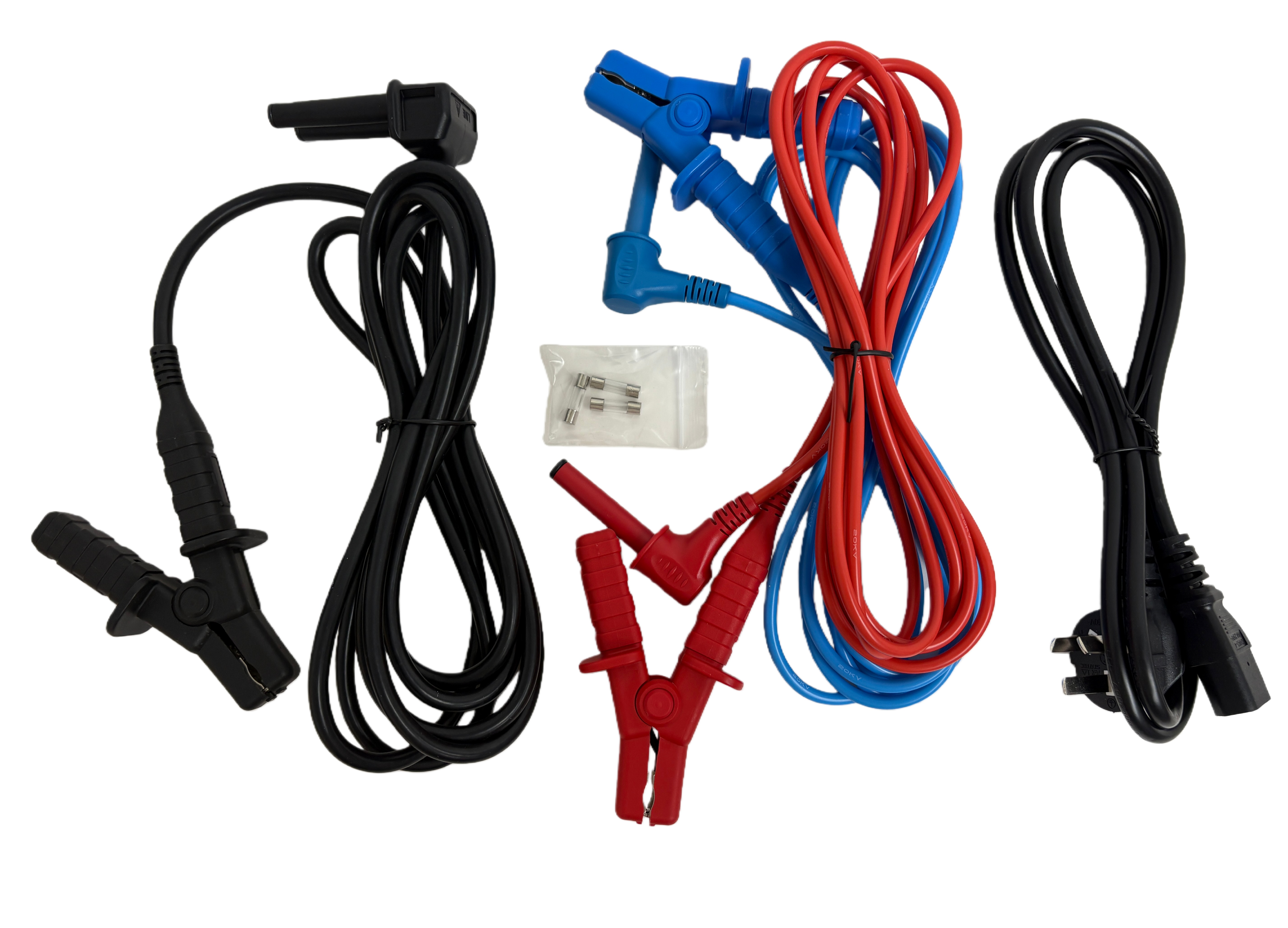
The required test leads, connection method, and compatible accessories.
PC software compatibility and available data export options.
User manual, operation guidance, and training requirements.
Warranty terms, technical support, and after-sales service arrangements.
For product selection or technical questions, contact the Wrindu team.