High Quality Transformer Tan Delta Test Kit



- Wrindu
- Shanghai, China
- about 10 working days
- 1000 set/month
- RD6000C
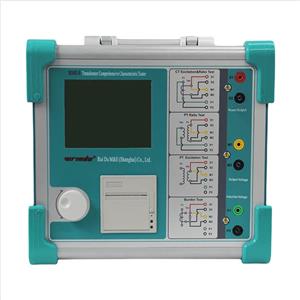
The RD6000C Transformer Tan Delta Test Kit uses frequency-conversion power technology instead of the traditional bridge measurement method. A built-in microprocessor and modern electronic components handle frequency switching, signal conversion, and data processing automatically.
Product Description
RD6000C Transformer Tan Delta Test Kit Achieves strong anti-interference ability, fast testing speed, high accuracy, fully automatic digitization, and easy operation; automatic filter 50Hz interference, suitable for field testing of large electromagnetic interference such as substations. It is widely used in dielectric loss measurement of the transformer, transformer, bushing, capacitor, arrester, and other equipment in the power industry.
Product Features
1. Accurate Measurement: The instrument uses digital Fourier transform filtering to measure capacitance, dielectric loss, and related parameters. It processes the test data automatically to provide accurate results.
2. Strong Interference Resistance: Frequency conversion technology helps reduce interference from the 50 Hz power supply. This supports stable measurements in substations and other environments with strong electromagnetic interference.
3. Touchscreen Operation: A full-color LCD touchscreen provides a clear operating interface. Operators can select the test mode, start measurements, and view results directly on the screen.
4. Test Data Storage: A built-in clock and internal memory store test results for later review. The instrument also records the test date and time, making it easier to organize measurement records.
5. USB Data Export: Test data can be transferred to a USB drive and managed on a computer using the supporting software.
6. Automatic Testing: After the operator selects the appropriate measurement mode, the built-in microprocessor controls the test process and completes the measurement automatically.
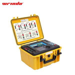
7. Integrated Design: The instrument combines a standard capacitor and high-voltage power supply in one unit. This design reduces external wiring and makes on-site testing more convenient.
8. AC Withstand Voltage Testing: The instrument can perform AC withstand voltage tests on PTs and CTs, as well as withstand voltage tests in 400 V low-voltage systems, subject to the instrument's rated output and approved test procedure.
9. External Power Frequency Identification: The instrument can identify external high-voltage power frequencies from 40 Hz to 70 Hz. It supports dielectric loss testing with power-frequency supplies or series-resonant power supplies, including applications involving high-capacitance test objects, within the instrument's rated limits.
10. On-Site Printing: A built-in thermal printer allows operators to print test results directly. The calendar clock records the test time, while USB output supports electronic recordkeeping.
11. Grounding and Overcurrent Protection: The instrument checks the grounding condition before entering the normal test procedure. It prevents high-voltage output when grounding is missing or inadequate and provides overcurrent protection if the test object is short-circuited or breaks down.
12. Electric Shock Protection: If an electric shock protection event is detected, the instrument cuts off the high-voltage output to help protect the operator. Proper grounding, isolation, and approved safety procedures remain essential during testing.
For more information about Transformer Testing Equipment, click the transformer testing list.
Product Specifications and Technical Parameters
Parameter | Specification |
|---|---|
Measurement Accuracy | Capacitance (Cx): ±(reading × 1% + 1 pF) |
Dielectric Loss (tan δ): ±(reading × 1% + 0.00040) | |
Anti-Interference Performance | Frequency-conversion anti-interference; maintains specified accuracy under 200% interference |
Capacitance Range (Internal High Voltage) | 3 pF–60,000 pF at 10 kV; 60 pF–1 μF at 0.5 kV |
Capacitance Range (External High Voltage) | 3 pF–1.5 μF at 10 kV; 60 pF–30 μF at 0.5 kV |
Capacitance Resolution | Up to 0.001 pF; 4 significant digits |
Dielectric Loss (tan δ) Range | Unlimited |
Dielectric Loss Resolution | 0.001% |
Automatic Identification | Capacitance, inductance, and resistance |
Test Current Range | 10 μA–5 A |
Internal High-Voltage Setting Range | 100 V–10 kV, adjustable |
Internal High-Voltage Setting Resolution | 1 V |
Maximum Internal High-Voltage Output Current | 200 mA |
Single-Frequency Test Range | 40.0–70.0 Hz |
Frequency Resolution | 0.1 Hz |
Automatic Dual-Frequency Testing | Adjustable around 50 Hz (±0.1 Hz to ±10 Hz) and 60 Hz (±0.1 Hz to ±10 Hz) |
External High-Voltage UST Mode | Maximum test current: 5 A; frequency: 40–70 Hz |
External High-Voltage GST Mode | Maximum test voltage: 10 kV; maximum test current: 5 A; frequency: 40–70 Hz |
Measurement Time | Approximately 40 seconds, depending on the test method |
Power Supply | 220 V AC, 50 Hz ± 1% |
Communication Interfaces | RS232, USB |
Printer | Mini thermal printer |
Operating Temperature | −10°C to +50°C |
Relative Humidity | Below 90% |
How Does the RD6000C Transformer Tan Delta Test Kit Assess Insulation?
The RD6000C measures capacitance and dielectric loss (tan delta) to help engineers assess the condition of electrical insulation. These parameters can reveal changes in dielectric performance that may require further investigation.
Tan delta, also known as the dissipation factor, reflects dielectric losses under AC voltage. An increase in tan delta may be associated with moisture, contamination, insulation aging, or other changes in the insulation system. However, the result alone cannot identify a specific defect.
The RD6000C is designed for dielectric loss measurements on transformers, bushings, capacitors, surge arresters, and other supported electrical equipment. Engineers should select the test connection, voltage, and evaluation criteria according to the equipment design and applicable test procedure.
How Do You Perform a Tan Delta Test with the RD6000C?
Step 1: Prepare the equipment. De-energize and isolate the test object, verify the absence of voltage, and follow the required grounding and lockout/tagout procedures.
Step 2: Check the connections. Inspect the test leads and grounding connections. Select the appropriate measurement mode and connection method for the equipment under test.
Step 3: Set the test parameters. Select the test voltage and frequency according to the approved procedure. Confirm that the expected capacitance and test current fall within the instrument's specified limits.
Step 4: Run the measurement. Start the test through the touchscreen interface. The specified measurement time is approximately 40 seconds, depending on the test method and conditions.
Step 5: Review and record the results. Record the measured capacitance, tan delta, test voltage, frequency, equipment identification, and relevant environmental conditions. Compare the results with historical data and applicable acceptance criteria.
Step 6: Save the test records. Use the instrument's internal storage, thermal printer, or USB interface to retain results for maintenance records and future comparison.
High-voltage testing must be performed by qualified personnel using the approved procedure and appropriate safety measures.
How Should Engineers Interpret Transformer Tan Delta Test Results?
A tan delta result should be evaluated in the context of the equipment type, test voltage, frequency, temperature where relevant, and applicable acceptance criteria. A single measurement should not be used as the sole basis for diagnosing insulation failure.
Comparing current measurements with historical records can help engineers identify changes in insulation performance. A significant change may justify further inspection or additional diagnostic tests.
The applicable test standard depends on the equipment and the purpose of the measurement. Engineers should follow the relevant standard, equipment manufacturer's instructions, and approved maintenance procedure when selecting test conditions and evaluating results.
Quality Assurance and Technical Support for the RD6000C
Reliable insulation testing depends on suitable test equipment, correct operating procedures, and proper result interpretation. Before using the RD6000C, operators should review the product manual, verify the test connections, and confirm that the selected parameters meet the requirements of the test object.
For product selection and technical evaluation, customers can contact Wrindu to confirm the applicable measurement ranges, test modes, operating conditions, and documentation requirements.
Wrindu should provide verified information about the RD6000C's factory inspection, calibration options, warranty coverage, and technical support services to help customers evaluate the instrument for their applications.