Transformer Winding Deformation: Causes and Solutions
I. Winding Faults Are a Significant Issue
According to data, transformer winding faults are relatively high in various statistics. Faults such as short-circuit impact currents (electromotive forces) can cause winding deformation, which is a significant cause of winding issues and warrants in-depth research into control measures.
Statistics show:
CIGRE statistics on 800 global transformer failures indicate winding issues account for about 20%.
The China Energy Bureau’s 10-year transformer failure statistics show an average of 10% are due to transformer winding faults.
In one region from 1990-1997, approximately 145 transformer failures at 110KV and above were directly caused by short-circuit fault current impacts, accounting for 31% of total accidents during the same period.
II. Causes of Transformer Winding Deformation
According to CIGRE Guideline 342 and the power industry standard DL/T911 “Frequency Response Analysis Method for Power Transformer Winding Deformation,” winding deformation refers to the axial or radial dimensional changes in power transformer windings under the action of mechanical or electromagnetic forces, typically manifesting as local distortion, bulging, or displacement of the windings.
Therefore, the main causes of winding deformation are electromagnetic or mechanical forces.
III. Mechanical Force Sources of Transformer Winding Deformation
Research and experience suggest that the main sources include:
1. Structural or production process issues.
2. Over-excitation, magnetic leakage, or abnormal core vibration.
3. Shock, jolting, or vibration during transportation.
4. Impact during installation or major overhaul.
5. Short-circuit current impact and inadequate winding capacity to withstand short circuits.
IV. How to Check for Winding Deformation
After local mechanical deformation of transformer windings, the internal inductance and capacitance distribution parameters necessarily undergo relative changes. This is the basis for conducting transformer deformation tests. Conventional methods (such as measuring ratio, direct resistance, and capacitance) are difficult to diagnose transformer winding deformation due to their low sensitivity. Dismantling for inspection requires a significant investment of manpower, material resources, and finances, and it’s also difficult to determine if the inner windings are deformed.
The main methods for winding deformation testing are:
1. Impedance Method
The impedance method is one of the earliest methods used to test winding deformation. It measures the transformer winding’s impedance or leakage reactance at 50Hz. Changes in these values are used to judge if the transformer winding has undergone deformation that could endanger operation, such as inter-turn short circuits, open circuits, or coil displacement.
National and IEC standards specify limits for changes in leakage reactance under rated current. IEC suggests that over 3% is abnormal, while national standards consider 2%-4% depending on the coil structure. Field experience shows that it’s challenging to achieve rated current conditions (especially for large transformers), and high test instrument accuracy is required, often making it difficult to obtain the necessary detection sensitivity. However, the impedance method is simple to implement and has standards to follow, making it a complementary means, especially for medium and low voltage transformers.
2. Low Voltage Impulse Method (LVI)
The Low Voltage Impulse method was first proposed in Poland in 1966 and later improved by the UK and the USA. It is primarily used to determine if a transformer has passed a short-circuit test and is included in IEEE guidelines and test standards. LVI overcomes the low sensitivity of the impedance method and can detect winding bends of 2-3mm. However, it uses time-domain pulse analysis technology, which has poor interference resistance in the field. The arrangement of dual-shielded cables, grounding wires, and surrounding objects can all affect test results. It is also prone to sensitivity calibration issues and requires a special test system with fine adjustments to eliminate pulse transmission problems and instability issues, often leading to poor repeatability in the field.
3. Frequency Response Method (FRA)
Frequency Response Analysis (sweep frequency measurement technology) measures transformer winding deformation and was first introduced in China in 1994. Proposed by E.P.Dick in Canada in 1978, it has been widely used in various countries and is considered effective in quickly detecting winding deformation equivalent to a 0.2% change in short-circuit impedance and a 0.3% change in axial size without dismantling the transformer. Compared to LVI, FRA uses advanced sweep frequency measurement technology, measuring high amplitude,known frequency, and below 1MHz sine wave signals, making it easy to eliminate interference using digital processing technology. The problem of signal reflection during propagation is also easily solved, providing strong interference resistance and ensuring the repeatability of measurement results.
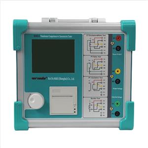
V. Introduction to Winding Deformation Monitoring and Analysis Equipment
The Transformer Winding Deformation Tester works on the principle of the Frequency Response Method (FRA).
The system’s basic components are managed and controlled by a computer, as shown in the diagram below:
The sweep signal generator sequentially applies different frequency sine wave voltage signals Vs(t) to the end of the transformer winding, and the high-speed acquisition system simultaneously records the voltage signal waveforms Vi(t) and Vo(t) at the corresponding starting end, and performs the corresponding digital processing to obtain their amplitude and phase at different scanning frequencies. Then, the amplitude-frequency response characteristic or phase-frequency response characteristic of the winding being tested is obtained according to the following formulas:
Amplitude-Frequency Response Characteristic:
H(f)=20log[Avo(f)/Avi(f)]
Phase-Frequency Response Characteristic:
φ(f)=φvo(f)-φvi(f)
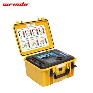
To summarize, we would like to introduce to you the RDRB-IV Winding Deformation Analyzer from Wrindu Company!

This product has the following advantages:
1. Frequency sweep method measures transformer winding characteristics without dismantling, identifying issues like distortion in 6kV+ transformers.
2. This portable frequency response analyzer rapidly assesses individual windings in just over a minute.
3. It guarantees high-frequency accuracy better than 0.001%.
4. Utilizes digital frequency synthesis for reliable frequency control.
5. The analyzer provides 5000 V of voltage isolation, ensuring the safety of the computer system during tests.
6. It can capture and analyze 9 contours automatically, diagnosing winding issues comprehensively.
7. The included software is powerful and compliant with national standards DL/T911-2016/IEC60076-18.
8. The software offers a user-friendly monitoring experience with one-click measurement execution.
9. The software interface is straightforward, with clear options for analysis, saving, reporting, and printing.
VI. Testing Precautions
Reliable testing is the basis for judging transformer winding deformation. Although the frequency response method is a highly sensitive winding deformation diagnostic method that can detect weak winding deformation phenomena and is basically unaffected by external stray interference signals, any changes in the electrical parameters of the test circuit will be sensitively reflected in the frequency response characteristics. Therefore, to achieve good results, the following issues must be considered.
◾ Requirements for the Test Environment:
If there is static electricity in the transformer winding, it will not only affect the frequency response characteristics, sometimes even making it impossible to ensure the repeatability of test results before and after; on the other hand, it may damage the test instrument. Therefore, before the test, the line ends of the transformer should be fully discharged. It is best to arrange the winding deformation test before all DC test items (such as winding DC resistance test, leakage current test).
◾ Requirements for Grounding:
Grounding is very important during the measurement process. In addition to protecting the instrument and equipment, it is mainly to ensure that the direction of high-frequency current flow is correct, otherwise, the measurement results will not be consistent. The transformer core must be reliably grounded to the case. The shell of the measuring impedance and the shell of the test instrument must be reliably grounded to the transformer shell. If the contact is poor, the frequency response curve may show abnormal phenomena such as burrs.
◾ Requirements for Transformer Status:
Requirements for leads, surrounding grounding bodies, and metal suspended objects. Winding deformation tests should be carried out under the condition that all leads of the transformer (including overhead lines, enclosed busbars, and cables) are disconnected. The transformer lead’s stray capacitance to the ground is often not fixed, and it will not be completely balanced between the three phases. The lead stray capacitance will change the frequency response characteristic curve. To ensure the repeatability of the test results and obtain accurate diagnostic results, all leads connected to the transformer bushing should be removed, and these leads should be as far away from the transformer bushing as possible (surrounding grounding bodies and metal suspended objects should be more than 20cm away from the transformer bushing), to reduce the influence of stray capacitance. This is especially true for transformers connected to enclosed busbars.
Requirements for the position of the tap changer. The frequency response characteristic of the winding is related to the position of the tap changer. When the position of the tap changer is different, there is a significant difference in the spectrum diagram. The position of the tap changer must be recorded correctly during the test. It is best to place the tap changer of the transformer being tested at the first tap to obtain more comprehensive winding information, especially for on-load tap-changing transformers. For off-load tap-changing transformers, it is necessary to ensure that the measurement is at the same tap position each time for comparison.