Other Necessary Tests about Transformer
In previous article, we talked about some necessary tests for transformers, focusing on insulation resistance measurement, dielectric loss factor and capacitance measurement, and partial discharge testing. Next, we will talk about other necessary tests about transformer.
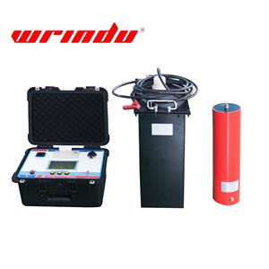
AC Withstand Voltage Test of Transformer
The AC withstand voltage test of the transformer should comply with the following regulations:
1. The test should be conducted at 80% of the factory test voltage, and the applied voltage should be monitored on the high-voltage side.
2. For oil-immersed transformers with voltage levels of 66 kV and above, a chromatographic analysis of the insulating oil should be performed before and after the AC withstand voltage test.
3. Electromagnetic voltage transformers (including the electromagnetic unit of capacitor voltage transformers) should undergo an induction withstand voltage test in accordance with the following provisions:
1) The test power frequency and test voltage application time must comply with the requirements standards. The test voltage waveform should be close to sine, and the test voltage value should be the peak value of the measured voltage divided by √2. The test should be conducted at the high voltage end. At the same time, during the induced voltage test, the frequency of the test voltage should be greater than the rated frequency. When the test voltage frequency is less than or equal to 2 times the rated frequency, the test time at full voltage is 60s; when the test voltage frequency is greater than 2 times the rated frequency, the test time at full voltage should be calculated according to the following formula:
t=120*(fN/fs)
fN——Rated frequency
fs——Test frequency
t——The test time at full voltage should not be less than 15s.
2) Before and after the induced voltage withstand test, the no-load current should be measured at rated voltage. The two measured values should not differ significantly.
3) When conducting an induced voltage withstand test on the intermediate voltage transformer of a capacitor voltage transformer, the coupling capacitor voltage divider, damper, and limiter should be disassembled. If disassembly is not possible on-site due to product structural reasons, the induced voltage withstand test may not be performed.
4. For SF6 gas-insulated transformers with voltage levels above 220kV, especially those with voltage levels of 500kV, it is advisable to carry out AC withstand voltage test after installation. Before the withstand voltage test, it is advisable to carry out an aging test under Um voltage for 15 minutes.
5.The power frequency withstand voltage test voltage between secondary windings and between secondary windings and the tank (ground) should be 2kV. This can be replaced by measuring the insulation resistance with a 2500V megohmmeter.
6. For current transformer terminals and voltage transformer grounding terminals (N) of voltage levels 110kV and above, the power frequency withstand voltage to ground should be 2kV. This can be replaced by measuring the insulation resistance with a 2500V megohmmeter.
Insulation dielectric performance test of Transformer
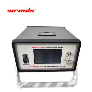
The instrument transformer filled with SF6 gas should be placed in a static state for 24 hours before sampling and testing. The moisture content of the gas should not be greater than 250μL/L (volume percentage at 20℃). For the 750kV voltage level, the moisture content of the gas should not be greater than 200μL/L.
If the insulation performance of oil-immersed transformers with a voltage level of 66 kV or above is in doubt, a chromatographic analysis of the dissolved gases in the oil should be performed. The total hydrocarbon content of the dissolved gas components in the oil should not exceed 10 μL/L, the H2 content should not exceed 100 μL/L, and the C2H2 content should not exceed 0.1 μL/L.
Winding DC resistance measurement
Voltage transformers: The measured DC resistance of the primary winding should not differ by more than 10% compared to the factory value converted to the same temperature. The measured DC resistance of the secondary winding should not differ by more than 15% compared to the factory value converted to the same temperature.
Current transformers: The DC resistance of current transformer windings of the same model, specification, and batch should not differ from the average value by more than 10%. When the primary winding is connected in series or parallel, the DC resistance of the current transformer's primary winding should be measured under normal operation, or the DC resistance of the primary winding under both connection methods should be measured simultaneously. The difference between the DC resistance of a single-turn primary winding of an inverted current transformer should not exceed 30%. When in doubt, the applied measuring current should be increased. The measured current (DC value) should not exceed 50% of the rated current (RMS value).
Transformer error and ratio measurement
1. Instrument transformers used for gateway metering (including current transformers, voltage transformers, and combination transformers) should undergo error measurement.
2. For instrument transformers used for non-gateway metering, the transformer ratio should be checked and ensure it matches the manufacturer's nameplate value. For multi-tap transformers, only the ratio of the tapped connections may be checked.
Measuring the excitation characteristic curve of the current transformer
1. When relay protection requires the excitation characteristics of the current transformer, the excitation characteristic curve should be measured.
2. When the current transformer has multiple taps, the tap currently in use or the tap with the maximum ratio should be measured. After measurement, compliance with product specifications should be verified.
3. If the applied voltage during the excitation characteristic measurement exceeds the allowable winding value (peak voltage 4.5kV), the test power frequency should be reduced.
4. For stand-alone, GIS, and bushing-type current transformers of 330 kV and above, busbar current transformers of 300 MW and above, and substation current transformers with transient characteristics exceeding 1200 MW at all voltage levels, windings with transient characteristic requirements should have their relevant parameters measured using the AC method (low-frequency method) or the DC method according to the nameplate parameters, and verification should be conducted to verify compliance with the requirements.
Excitation Curve Measurement of Electromagnetic Voltage Transformer
1. The instrument used for excitation curve measurement should be an RMS meter. If the measurement results differ by more than 30% from the factory test report or type test report, verify the correct instrument type.
2. Excitation curve measurement points should include 20%, 50%, 80%, 100%, and 120% of the rated voltage.
3. For voltage transformers with a directly grounded neutral point, the highest measurement point should be 150%.
4. For systems with a non-directly grounded neutral point, the highest measurement point for semi-insulated electromagnetic voltage transformers should be 190%, and for fully insulated electromagnetic voltage transformers, the highest measurement point should be 120%.
Capacitive voltage transformer CVT detection
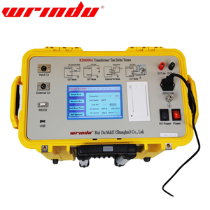
1. The capacitance of the CVT capacitor divider should not exceed -5% to 10% of the rated capacitance, and the dielectric loss factor (tanδ) should not exceed 0.2%.
2. If the stacked CVT electromagnetic unit makes it difficult to lead out the medium-voltage connection due to structural reasons, capacitance and dielectric loss factor (tanδ) tests may not be performed, but an error test should be performed. If the error test results do not meet the error limit requirements, the electromagnetic unit medium-voltage connection line should be disconnected, and the capacitance and dielectric loss factor (tanδ) of each electromagnetic unit component and the capacitor divider should be tested.
3. The CVT error test should be performed on a bracket (column).
4. If the electromagnetic unit structure permits, the electromagnetic unit inspection should include measurement of the intermediate transformer excitation curve, measurement of the compensating reactor inductance, and performance checks of the damper and limiter. The AC withstand voltage test should be performed as for an electromagnetic voltage transformer, with the applied voltage at 80% of the factory test.
Sealing performance inspection
1. The surface of oil-immersed transformers should be free of visible oil stains.
2. For gas-insulated transformers, qualitative leak testing should reveal no leak points. If leaks are suspected, quantitative leak testing should be performed. The annual leakage rate should be less than 1%.
If you have any questions about transformer, please contact us.


