Necessary Tests about Transformer
What do you know about Transformer?
A transformer, also known as a voltage transformer or a current transformer, is a special transformer used to convert high voltage or large current into low voltage and small current that are easy to measure.
Voltage Transformer (VT)
A voltage transformer can convert high voltage into low voltage and are used to measure line voltage and protect lines. The primary side of the voltage transformer is connected in parallel in the voltage circuit to be measured, and the secondary side is connected to measuring instruments, relays, etc.
Current Transformer (CT)
A current transformer can output a large current as a measurable small current. At the same time, the primary side is connected in series in the circuit loop being measured, and the secondary side must remain closed to avoid high voltage generated by an open circuit.
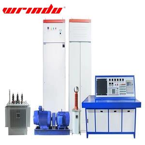
Transformer Testing
According to our Technical staff, Transformer testing should include at least the following items:
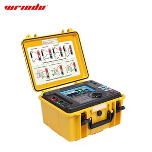
1. Insulation resistance measurement
2. Measure the dielectric loss factor and capacitance of transformers with voltage levels of 35KV and above
3. Partial discharge test
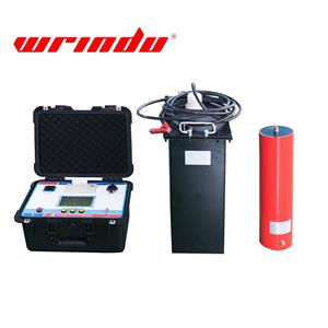
4. AC withstand voltage test
5. Insulation dielectric performance test
6. Measuring the DC resistance of the winding
7. Check the wiring winding group and polarity
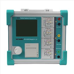
8. Error and ratio measurement
9. Measuring the excitation characteristic curve of the current transformer
10. Measuring the excitation characteristics of electromagnetic voltage transformers
11. Capacitor Voltage Transformer (CVT) Testing
12. Sealing performance test
Voltage Transformer(VT)
Except for the standard for current transformers in NO.9, the voltage transformer test should include all the remaining contents.
Current Transformer(CT)
Except for the standard for current transformers in NO.10 and NO.11, the current transformer test should include all the remaining contents.
Voltage transformer in SF6 enclosed combination
The test should comply with the above item NO.6, 7, 8 and 12. In addition, the insulation resistance between the secondary windings and to the ground, the primary winding grounding terminal and the secondary winding AC withstand voltage test must be carried out. When the line permits, the experiment can be carried out according to the above item NO.3 and NO.10. The configured pressure gauge and density relay inspection can be carried out according to the GIS experiment content.
Current transformer in SF6 enclosed combination
The test should follow the above NO.7, 8, 9, and the secondary winding should be tested according to NO.1 and NO.6.
Measuring the insulation resistance of windings
1. Measure the insulation resistance between the primary and secondary windings and the casing, and between each secondary winding and the casing. The insulation resistance value should not be less than 1000 MΩ.
2. Measure the insulation resistance between segments of the primary winding of a current transformer. The insulation resistance value should not be less than 1000 MΩ. This measurement is not necessary if structural reasons make it impossible.
3. Measure the insulation resistance between the terminal plate of a capacitor-type current transformer and the ground terminal (N) of a voltage transformer and the casing (ground). The insulation resistance value should not be less than 1000 MΩ. If the terminal plate insulation resistance to ground is less than 1000 MΩ, measure its tan8 value. The value should not exceed 2%.
4. Use a 2500V megohmmeter to measure the insulation resistance.
Measure the dielectric loss factor and capacitance of transformers with voltage levels of 35KV and above
tan δ (%) Limit(t:20℃)
| Rated voltage | 20~35 | 66~110 | 220 | 330~750 |
| Oil-immersed current transformer | 2.5 | 0.8 | 0.6 | 0.5 |
| Silicone grease filled and other dry type current transformers | 0.5 | 0.5 | 0.5 | — |
| Oil-immersed voltage transformer as a whole | 3 | 2.5 | — | |
| Oil-immersed voltage transformer end screen | — | 2 | ||
The transformer winding tanδ measurement voltage should be 10kV, and tanδ (%) should not be greater than the data in the above table. When there is doubt about the insulation performance, the high voltage method can be used for testing within the range of (0.5~1)Um/√3, where Um is the highest voltage of the equipment (root mean square value). The change in tanδ should not be greater than 0.2%, and the change in capacitance should not be greater than 0.5%.
For inverted oil-immersed current transformers with secondary coil shield directly grounded, the reverse connection method should be used to measure tan delta and capacitance.
The end screen tanδ measurement voltage should be 2kV.
If the capacitance of a capacitor-type current transformer exceeds 5% of the factory test value, the cause should be identified.
Partial discharge measurement of transformers
1. Partial discharge measurements should be conducted simultaneously with AC withstand voltage tests.
2. Partial discharge measurements can be conducted on 10% of instrument transformers with voltage levels of 35kV to 110kV.
3. Partial discharge measurements should be conducted on instrument transformers with voltage levels of 220kV and above when the insulation performance is questionable.
4. During partial discharge measurements, the applied primary voltage should be monitored on the high-voltage side (including the induced voltage of electromagnetic voltage transformers).
5. The measurement voltage and the permissible apparent discharge level for partial discharge measurement shall be determined according to the following table:
| Categories | Measuring voltage(kV) | Allowable apparent discharge level(pC) | |||
| Epoxy resin and other dry | Oil-immersed and gas-immersed | ||||
| Current Transformer | 1.2Um/√3 | 50 | 20 | ||
| Um | 100 | 20 | |||
| Voltage Transformer | ≥66kV | 1.2Um/√3 | 50 | 20 | |
| Um | 100 | 50 | |||
| 35kV | Fully insulated structure (primary windings are connected to high voltage) | 1.2Um | 100 | 50 | |
| Semi-insulated structure (one end of the primary winding is directly grounded) | 1.2Um/√3 | 50 | 20 | ||
| 1.2Um(if necessary) | 100 | 50 | |||
Um is the maximum voltage of the equipment (RMS value)
In next article,we will focus on AC withstand voltage test, Insulation dielectric performance test, Measuring the DC resistance of the winding, Check the wiring winding group and polarity, Error and ratio measurement, Measuring the excitation characteristic curve of the current transformer, Measuring the excitation characteristics of electromagnetic voltage transformers, Capacitor Voltage Transformer (CVT) Testing and Sealing performance test.