CT and PT Testing Procedure
How to Test CT and PT?
To begin with, let's talk about what is CT and PT. If you think the CT scans here are the same as the ones we took in the hospital, you are totally wrong.
CT means current transformers. A Current Transformer is an instrument transformer with its primary winding connected in series with the conductor carrying the current we want to measure or control. CT are used to supply a reduced value of current (5 or 1A at full load) to meters, protectiverelays, and other instrumentation, protect personnel and apparatus from high voltage while allowing areasonable amount of current in each of these applications. In addition, the secondary of the transformer will supply a current that accurately reflects aproportional value of the primary current with the smallest phase shift possible.
CT is used for metering have to maintain a high degree of accuracy over the full range of current levels from 10% to 100% of the full load CT rating. The measurement and billing of energy usage relies on inputs provided by CT metered installations. Revenue loss due to inaccurate metering is a significant concern for electrical utilities.
PT means potential transformer. Usually, it can be called voltage transformer (VT) as well. VT is an instrument used in power systems to reduce high voltage to a lower and safer level for measurement.
A voltage transformer is similar to a power transformer, or rather, very similar. It has a primary winding. Unlike a current transformer, which has a secondary winding, a voltage transformer has a primary conductor that actually serves as the primary winding. It has a magnetic core, usually a round core, wound with magnetic wire, which forms the windings.
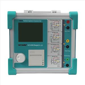
The purpose of the CT and PT test procedures is to verify the performance and accuracy of current transformers (CTs) and potential transformers (PTs). Key tests include polarity, turns ratio, insulation resistance, and knee voltage (for CTs) or excitation testing (for PTs). These tests ensure that the transformers are operating within acceptable limits and are properly connected to the circuit.
Now, you have a basic understanding of CT and PT. So let's go back to the topic.
CT Testing Procedure
1. Visual Inspection:
Begin by visually inspecting the CT for any physical damage, defects, or loose connections.
Ensure there is no visible wear or environmental damage that could affect performance.
2. Secondary Circuit Verification:
Before conducting electrical tests, check the secondary circuit connections (including shorting and isolating links) to ensure proper grounding and functionality.
3. Insulation Resistance Test:
Use a Megger to measure the insulation resistance between the CT windings and the ground. This step ensures the proper isolation and safety of the CT.
4. Winding Resistance Measurement:
Verify the resistance of both the primary and secondary windings using a micro-ohmmeter. This ensures that there are no shorts or issues within the windings.
5. Polarity Test:
Confirm the correct polarity of the CT by injecting current into the primary and measuring the induced current in the secondary. This test ensures that the CT is wired correctly and will function properly in the system.
6. Ratio Test:
Inject current into the primary and measure the corresponding secondary current to determine the CT's ratio (primary to secondary current). This is critical for the CT’s accuracy in current measurement.
7. Excitation (Saturation) Test:
Gradually increase the voltage on the secondary winding and observe the resulting current. This helps identify the CT’s saturation point, ensuring that it will operate effectively without distortion in high-current situations.
8. Demagnetization:
After testing, apply a voltage above the knee-point voltage and gradually reduce it to zero to demagnetize the CT core, preventing residual magnetism that could affect future performance.
VT Testing Procedure
1. Visual Inspection:
Begin by visually inspecting the VT for any physical damage, defects, or loose connections. This ensures that the transformer is in good condition before electrical testing.
2. Neutral Grounding Verification:
Ensure that the VT’s neutral is properly grounded to avoid any safety risks during testing and operation.
3. Winding Resistance Test:
Measure the resistance of the VT windings. This helps check for continuity and any internal short circuits or winding issues.
4. Insulation Resistance Test:
Use a Megger to measure the insulation resistance between the VT windings and ground. This step confirms that there is adequate insulation and isolation to prevent electrical faults.
5. Polarity Check:
Verify the correct polarity of the VT by observing the voltage relationships between primary and secondary terminals. This ensures the VT is wired correctly and will function properly in the system.
6. Ratio Check:
Inject a voltage into the primary winding and measure the corresponding voltage on the secondary. This helps to verify that the VT’s ratio (primary to secondary voltage) matches the specified value.
7.Burden Test:
Test the VT’s ability to handle the connected burden (load) without excessive voltage drop. This step ensures the VT can maintain its accuracy and performance under typical operating conditions.

A suitable current, below saturation, is applied tothe primary winding, and the secondary current ismeasured.
The turns ratio is approximately equal to the ratioof primary current to the measured secondarycurrent.
Ratio Test-Voltage Method
A suitable voltage, below saturation, is applied to the secondary winding, and the primary voltage is measured. The turns ratio is approximately equalto the ratio of the secondary voltage to measure primary voltage.
For metering applications: +0.1% for ratio and +0.9mrad (3min) for phase angle.
For other applications: +1.2% for ratio and ±1 degree for phase angle.

Welcome to contact us for technical help.
Our products are easy to operate, reliable in performance, and can better meet the needs of transformer induction withstand voltage testing. Click here to find more information about CT and PT Analyzer.