10 questions to help you understand transformers in seconds!
1. What is a transformer?
A transformer is a device that uses the principle of electromagnetic induction to transform AC voltage. Transformers are basic equipment for power transmission and distribution and are widely used in industry, agriculture, transportation, urban communities and other fields.
2. What is the transformer used for?
The main function of a transformer is to increase or decrease the AC voltage to obtain the desired target voltage. In our daily lives, electricity is transported from power plants to thousands of households to power a variety of home appliances. In order to reduce the loss of long-distance electricity transportation, power plants output high-voltage electricity, up to hundreds of thousands of volts. However, the voltage required by home appliances is 220 volts, and some small appliances only require dozens of volts. At this time, the voltage needs to be changed through a transformer to adapt to various applications.
In addition, transformers also have functions such as current conversion, impedance conversion, isolation, and voltage stabilization (magnetic saturation transformer).
3. How does a transformer work? How does it work?
Simply put, the working principle of a transformer is "electricity generates magnetism, and magnetism generates electricity."
The main components of a transformer are a coil and an iron core (or magnetic core). The coil has two or more windings. The winding connected to the power supply is called the primary coil, and the remaining windings are called secondary coils. The function of the iron core is to strengthen the magnetic coupling between the two coils.

Transformers change voltage through the principle of electromagnetic induction. When the primary coil is supplied with alternating current, the transformer core generates an alternating magnetic field, and the secondary coil generates an induced electromotive force. This shows that the two sets of coils are only magnetically coupled but not electrically connected, but the secondary coil will have the same electromotive force as the primary coil. Think of both ends of the secondary coil as a new power source. When the circuit in the secondary coil is closed, an alternating current is generated.
4. How to calculate the transformer ratio?
Transformers can change voltage, but by how much?
In fact, the turns ratio of the transformer's coils is equal to the voltage ratio, that is:
U1/U2=N1/N2
In the formula, U1 and U2 are the voltages of the primary and secondary coils; N1 and N2 are the number of turns of the primary and secondary coils.
Transformers are static electrical appliances made using the principle of electromagnetic induction. When the primary coil of the transformer is connected to the AC power supply, alternating magnetic flux is generated in the core, and the alternating magnetic flux is represented by φ. Because φ in the primary and secondary coils is the same. According to Faraday’s law of electromagnetic induction, the induced electromotive force in the primary and secondary coils is:
e1=-N1dφ/dt
e2=-N2dφ/dt

The figure shows:
U1=-e1
U2=e2
Comprehensive available:
U1/U2=N1/N2
That is, the turns ratio of the transformer's coils is equal to the voltage ratio. For example: the primary coil has 500 turns, the secondary coil has 250 turns, and the primary is connected to 220V AC, the secondary voltage is 110V.
It is worth noting that the turns ratio of the transformer's coils is equal to the voltage ratio. This is the ratio under ideal conditions, indicating that the ideal transformer itself has no power loss. However, there are always losses in actual transformers, including copper losses (coil resistance heats up), iron losses (iron core heats up) and magnetic flux leakage (magnetic induction lines closed by air), etc.
5. What types of transformers are there?
Classified by voltage: there are low-voltage transformers, high-voltage transformers, and ultra-high-voltage transformers;
From the structural classification, there are double winding transformers, multi-winding transformers, split transformers, and auto-coupling transformers;
Classification by cooling method: air-cooled transformer, oil-cooled transformer, water-cooled transformer (very few);
Classification from the insulation medium: oil-immersed transformer, dry-type transformer, gas-insulated transformer;
Classified by the number of phases: single-phase transformers, three-phase transformers, and split transformers;
Classified by use: power transformers, special power transformers, voltage regulating transformers, measuring transformers (voltage transformers, current transformers), small power transformers (for small power equipment), and safety transformers.
6. What are the commonly used transformers?

7. What are the main parameters of the transformer?
Rated frequency: the operating frequency specified in the design of the transformer. Transformer core loss has a great relationship with frequency, so it should be designed and used according to the frequency of use. Represented by ƒN, the unit is Hertz (HZ). Our country stipulates that the rated frequency is 50HZ.
Rated capacity: refers to the output power of the transformer under working conditions, expressed in apparent power. Represented by SN, the unit is KVA or VA.
Rated voltage: refers to the voltage allowed to be applied to the coil of the transformer, which shall not exceed the specified value during operation. Represented by UN, the unit is KV or V. The primary rated voltage is represented by UN1, and the secondary rated voltage is represented by UN2.
Rated current: refers to the current passing through the outlet terminals of the primary and secondary windings of the transformer under the conditions of rated capacity and allowable temperature rise, expressed in IN, and the unit is KA or A. The primary winding current is represented by IN1, and the secondary winding current is represented by IUN21.
Rated power: Under the specified frequency and voltage, the output power of the transformer can work for a long time without exceeding the specified temperature rise.
8. How to select transformer?
First of all, we need to investigate the power supply voltage of the place where electricity is used, the actual power load of the user and the conditions of the place, and then select one by one according to the technical data marked on the transformer nameplate.
So how to determine the reasonable capacity of the transformer?
Generally, the transformer capacity, voltage, current and environmental conditions should be comprehensively considered. The capacity selection should be based on the capacity, nature and usage time of the user's electrical equipment to determine the required load, so as to select the transformer capacity.
During normal operation, the electrical load the transformer should bear is about 75 to 90% of the rated capacity of the transformer. When the actual load of the transformer is measured to be less than 50% during operation, the small-capacity transformer should be replaced. If the load is greater than the rated capacity of the transformer, the large-capacity transformer should be replaced immediately.
At the same time, when selecting a transformer, determine the voltage value of the primary coil of the transformer based on the line power supply, and select the voltage value of the secondary coil based on the electrical equipment. It is best to choose a low-voltage three-phase four-wire power supply. This can provide both power and lighting electricity at the same time.
When selecting the current, attention should be paid to whether the load can meet the requirements of the motor when it starts (because the starting current of the motor is 4 to 7 times larger than that of sinking operation).
9. What is the difference between low frequency transformer and high frequency transformer?
According to the different operating frequencies of transformers, they can generally be divided into low-frequency transformers and high-frequency transformers.
The main differences between the two include the following three points:
First the frequency is different. In daily life, the frequency of power frequency alternating current is 50Hz. We call transformers working at this frequency low-frequency transformers; while the working frequency of high-frequency transformers can reach tens to hundreds of kHz.
Secondly, the volume is different. For low-frequency transformers and high-frequency transformers with the same output power, the volume of the high-frequency transformer is much smaller than that of the low-frequency transformer. The transformer is a relatively large component in the power circuit. To ensure the output power while making the size small, a high-frequency transformer must be used, so high-frequency transformers are used in switching power supplies.
Also, the materials used in the cores are different. The core of low-frequency transformers is generally made of stacked silicon steel sheets, while the core of high-frequency transformers is made of high-frequency magnetic materials (such as ferrite). (So the iron core of high-frequency transformers is generally called magnetic core)
10.What is the nameplate of a transformer? What are the main technical data?
The nameplate of the transformer indicates the performance, technical specifications and usage occasions of the transformer to satisfy the user's selection. The main technical data that should be paid attention to during selection are usually:
(1) Kilovolt-ampere of rated capacity. That is, the output capacity of the transformer under rated conditions. For example, the rated capacity of a single-phase transformer = U line × I line; the capacity of a three-phase transformer = U line × I line.
(2) Rated voltage volts. Mark the terminal voltage of the primary coil and the terminal voltage of the secondary coil (when no load is connected) respectively. Note that the terminal voltage of the three-phase transformer refers to the line voltage U line value.
(3) Rated current amperes. It refers to the line current I line value that the primary coil and secondary coil are allowed to pass through for a long time under the conditions of rated capacity and allowable temperature rise.
(4)Voltage ratio. Refers to the ratio of the rated voltage of the primary coil to the rated voltage of the secondary coil.
(5), wiring method. Single-phase transformers only have one set of coils each for high and low voltage, and are only for single-phase use. Three-phase transformers have Y/Δ type. In addition to the above technical data, there are also the rated frequency, number of phases, temperature rise of the transformer, impedance percentage of the transformer, etc.
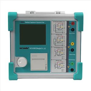
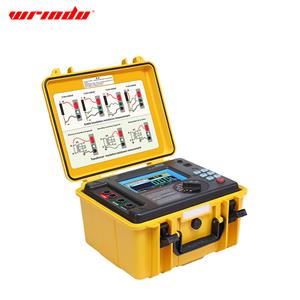
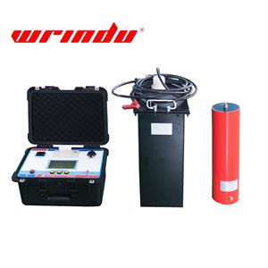
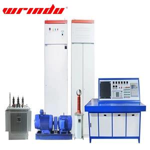
Professional transformers require professional transformer testers for preventive and regular inspections. Not only do we have Transformer ratio tester and Transformer winding deformation tester, we will also provide you with the best prices and services. Click on the yellow font to learn more about our products.