Withstand voltage test methods for different power cables
There are different kinds of power cables, such as oil-impregnated paper-insulated cables, plastic-insulated cables, and cross-linked polyethylene (XLPE) cables. They have different electrical characteristics which require different voltage withstand test methods. The following will introduce the common test methods for these cables, including DC voltage withstand tests, AC voltage withstand tests, ultra-low frequency voltage tests, partial discharge tests, and more.
DC Voltage Withstand Test for Oil-Impregnated Paper-Insulated Cables
The DC voltage withstand test is used to assess the leakage and voltage withstand characteristics of the insulation in oil-impregnated paper-insulated cables. Compared to the AC voltage withstand test, the DC voltage withstand test has the following advantages.
Convenient for Field Use: DC high voltage generators are lightweight and portable. It makes them ideal for onsite use.
Prevents Corona Discharge: The DC test avoids the occurrence of corona discharge in insulation voids, preventing permanent insulation damage.
Simultaneous Measurement of Leakage Current: Leakage current is measured during the DC voltage withstand test. By analyzing the current and its variation over time, we can assess the condition of the cable insulation. This is especially useful for detecting moisture or damage.
Exposes Moisture Defects: When negative polarity is applied in the DC test, moisture in the insulation moves toward the negative electrode. This increases leakage current and exposes defects in the insulation, particularly if the paper insulation is damp.
Shorter Test Duration: The DC voltage withstand test requires a shorter pressure application time. For cables rated between 6-35kV, the test usually lasts for just 5 minutes, enough to identify potential defects.
During the DC test, the leakage current changes over time. This reflects the insulation quality. If the leakage current increases over time or with voltage, it may indicate insulation defects.
Voltage Withstand Test for Cross-Linked Polyethylene (XLPE) Cables
DC voltage is still the primary test method for XLPE cables. However, it is not suitable for high-voltage XLPE cables, especially those rated above 150kV. There are several issues with using DC voltage tests for XLPE cables:
Uneven Electric Field Distribution: The electric field inside XLPE insulation behaves differently under DC and AC voltages. Under DC, the field is uneven because of the non-uniform resistivity of XLPE insulation. In contrast, the electric field distribution under AC is more stable.
Accelerated Water Treeing: DC voltage speeds up the development of water trees in XLPE cables. This can cause insulation aging and shorten the cable's service life.
Space Charge Formation: During the DC test, space charges build up within the insulation. This can lead to breakdowns when the cable is later subjected to AC operating voltage.
Therefore, ultra-low frequency voltage tests and AC frequency conversion series resonant tests are better suited for XLPE cables.
Ultra-Low Frequency Voltage Test
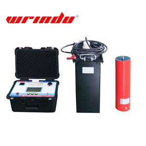
Frequency Range: The output frequency usually ranges from 0.01Hz to 0.1Hz. This reduces the size and weight of the test equipment while still being suitable for onsite testing.
Suitable Cables: This method is mainly used for medium-voltage (6-35kV) XLPE cables. The recommended test standard is 3U0/1h.
AC Frequency Conversion Series Resonant Test
Reducing Equipment Size: The series resonant frequency conversion test uses lower voltage and smaller equipment. This makes it ideal for onsite AC voltage withstand testing of XLPE cables.
Suitable for High Voltage Cables: This method is used for high-voltage XLPE cables (e.g., 220kV). It is an effective solution for field testing.
Partial Discharge Test for Plastic Cables
Plastic cables can experience partial discharges when there are air gaps, moisture, or defects in the insulation. Partial discharge testing helps identify potential insulation defects, especially in critical areas like cable joints or terminations. The focus of the test are as follows.
Partial Discharge Measurement: This test detects partial discharges in specific areas of the cable, such as suspected sections, mid-joints, and termination points, to evaluate the insulation's condition.
Impact Factors: If partial discharges occur briefly, they may not cause immediate breakdowns. However, they can still be harmful over time. Therefore, testing is essential to detect insulation defects in these critical areas.
Conclusion
| Test Method | Suitable for | Advantages | Limitations |
| DC Voltage Test | Rubber and plastic cables | Useful for detecting significant insulation deterioration or breakdown. | Destructive in nature, should only be used when necessary, and as a reference. |
| Ultra-Low Frequency High Voltage Test | Rubber and plastic cables (up to 35kV) | Easy-to-use device, does not damage cables, suitable for testing up to 35kV. | Limited to cables rated up to 35kV. |
| Frequency Conversion Resonant Test | Cables rated above 66kV | Suitable for high-voltage cables, reduces equipment size for onsite tests. | Field operation can be complicated for cables below 35kV. |
| Oscillating Voltage Methods | Cables rated 110kV and above | Compact and convenient for onsite use. | Effectiveness needs further verification compared to other tests. |
| Partial Discharge Tests | Cables rated 110kV and above | Critical for detecting insulation defects in cable joints and terminations. | |
| Dielectric Loss Measurement | Limited onsite use | Provides valuable insights into cable insulation properties. | Limited onsite applicability due to inherent limitations. |


