Is the data from your dielectric loss tester unreasonable?
Are you experiencing unreasonable measurement data when using the dielectric loss tester? The following 9 factors might be the cause.
Poor Hook Connection
When using hooks to connect the test specimen during field measurements, make sure the hook is in good contact with the specimen. Poor contact can cause discharge at the contact point, leading to significant data fluctuations! This is especially common when the grounding wire has a thick oxide layer or if the wire swings in the wind, causing bad contact.
Poor Grounding
Poor grounding can lead to instrument protection errors or severe data fluctuations. Ensure the grounding point is free from paint or rust, and guarantee a 0-ohm resistance ground connection!
Direct Measurement of CVT or End-Shielding Method for Electromagnetic PT
Directly measuring the coupling capacitor of the next stage in a CVT can result in negative dielectric loss. Switch to using the self-excitation method.
For electromagnetic PTs measured with the end-shielding method, humidity can cause "T-network interference," resulting in negative dielectric loss. Dry the lower three skirt ceramic sleeves and the terminal board. Alternatively, use the conventional method or the end-pressurizing method for measurement.
High Air Humidity
High humidity can cause abnormal increases (or decreases, even negative values) in dielectric loss readings, leading to instability. In some cases, you may need to add a shielding ring. However, adding a shielding ring changes the electric field distribution of the specimen, which is controversial. Please refer to the relevant regulations for guidance.
Generator Power Supply
When powered by a generator, unstable input frequency can affect measurements. It's best to use a fixed 50Hz frequency mode.
Testing Leads
Over time, testing leads may develop hidden open circuits, short-circuits between the core and shielding, or poor contact in the connectors. Regular maintenance of the testing leads is necessary.
When testing standard capacitors, use fully shielded connectors to eliminate stray capacitance interference, or the instrument accuracy will be affected.
When using the self-excitation method to measure CVTs, high-voltage wires not intended for this purpose should be suspended in the air to avoid stray capacitance to ground, which can introduce measurement errors.
Correct Measurement Mode Selection
After connecting the wires, ensure you select the correct measurement mode (Positive, Negative, or CVT). Choosing the wrong mode can lead to inaccurate readings. In environments with interference, it is especially important to choose the frequency-shifting anti-interference mode.
Influence of Testing Method
Dielectric loss measurements are highly affected by the testing method. Distinguish between testing method errors and instrument errors. When an issue arises, first check the wiring, and then check whether the instrument is malfunctioning.
Instrument Malfunction
Use a multimeter to check if the testing leads are open or if there's a short between the core and shielding. Check if the input power supply is too high or low (220V), and guarantee grounding is good.
Test the instrument with standard capacitors or known capacitive specimens to confirm if the readings are correct. If the results are correct, the instrument is likely fine.
If you disconnect all testing leads and perform a voltage rise test, and the instrument doesn't function properly, it could be faulty.
After starting the CVT measurement, check the low voltage output. It should show 2-5V. If not, the instrument may be malfunctioning.
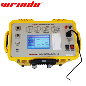
Click to find more information about RD6000A Tan Delta Tester.
The following relevant articles about tan delta of transformer are as follows.
What is the tan delta test on a transformer?


