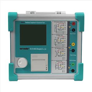
How to use Tan delta tester?
Step 1: Power on
Turn on the power switch, the instrument starts self-checking, if the self-checking is good, LCD screen displays the boot-up Interface, as shown in the figure below.

Step 2: Explanation of test parameter selection
1) Frequency: 50.0 ±5.0Hz represents the use of 45/55Hz dual frequency conversion test. Field testing is usually selected as 50 ±5Hz or 60 ± 5Hz. Of course, other frequency values can also be selected. If you want to test single frequency, such as 50Hz, you can choose 50.0 ± 0.0Hz. The frequency values is set within the range of 40-70 Hz.
2) Test Mode: GST (test mode used when testing). Click [ GST ] to display the drop-down menu, you can choose UST, GST, GSTG,AC HIPOT or CVT.
3) Test HV: 10000V represents the test voltage value. Minimum 100V, maximum 10000V. Voltage can be set at will here, such as 7892V.
4) HV Selection: HV-I: Internal high voltage represents the use of internal high voltage power supply. In general, it must be set to internal high voltage. HV-E: External high voltage is only used when external high voltage power supply is connected.
5) Cn Selection: Cn-I: Internal standard represents the use of internal standard capacitors. General testing must be set to internal standards. Cn-E: External standard is used only when external standard capacitor is used.
Note: External standard and external high voltage is used when large capacity or high voltage dielectric loss. The normal equipment of the substation can be tested by using the internal standard and internal high voltage of the instrument.
Step 3: Modification and selection of test parameters

1) Modification of test frequency, clicking on the red value "45.0" part of "45.0±0.0Hz" with a 12stylus or finger. as shown in the figure above. Input the frequency value of 50 directly from the keyboard, then click [ OK ]. If the frequency in the figure above is 45.0±0.0Hz, it will change to 50.0±0.0Hz after click [ OK ]. If you change the "0.0" part of "45.0±0.0Hz", click on the red value 0.0 with a stylus or finger. A keyboard appears, and then enter 5.0 from the keyboard, then click [ OK ].
2) The modification of the test voltage is the same as the modification frequency. Use a stylus or finger to click on the red value "10000V" part of "Test Voltage 10000V". The keyboard will display. Input the test voltage value of 5000 directly from the keyboard, then click [ OK ], the keyboard disappears. The value of the test voltage will become the value you just entered from the keyboard.
3) Modification of test mode, clicking on the [ GST ] with a stylus or finger, as shown in the figure below. All test modes are on the drop-down menu. Click on the mode you want to select.
4) The modification of high-voltage selection is the same as the modification of test mode. With a stylus or finger click on the [ HV-I ], the drop-down menu appears “HV-I” and “HV-E”, click on the mode you want to choose. 5) The modification of standard selection is the same as the modification of test mode. With a stylus or finger click on [ Cn-I ] , the drop-down menu appears “Cn-I” and “Cn-E”, click on the mode you want to choose.
Step 4: Prepare before measurement
1) One end of the grounding wire is connected with the grounding column of the instrument, and the other end is connected with the earth reliably to ensure that the instrument shell is on the ground potential.
2) UST test mode: insert the high-voltage cable plug into the HV socket of the back door, clamp the red pliers at the other end to the high-end lead of the tested product, and hang the black pliers or clamp them on the red pliers. Insert the Cx low voltage cable into the Cx socket, and the red clamp at the other end, the Black clamp suspended or connected with the shielding device at the lower end of the sample.
3) ST test mode: insert the high voltage cable plug into the HV socket of the back door, clamp the red pliers at the other end to the high-end lead of the tested product, and suspend the red pliers or connect the shielding device. Cx socket is not used.
Step 5:Testing process

Choose test items, test frequency, test voltage and so on, as shown in the figure above. After making sure the connection is correct, click [ Start Test] with a stylus or finger,the instrument starts to boost and measure. The instrument adopts dual frequency conversion test. Figure 3 is 55 Hz test and Figure 4 is 45 Hz test.


Step 6: Test Result


The capacitance and dielectric loss of C1 and C2 are the values of C1 and C2 of CVT equipment. The capacitance and dielectric loss values of CZ are the total capacitance and dielectric loss values of CVT equipment.
Step 7:After-test Check
1) Test data storage Test data can be stored after testing. Click on the [ Save ] button with a stylus or finger, as shown in the figure below.

A keyboard appears when you click on the value "1" in the data numbering box with a stylus or finger. as shown in the figure below.

Enter the storage number and click [ OK ], the keyboard disappear. Then click the [ Save ] and the instrument will beep and return to the test result interface. Represents that the storage is complete.
2) Test data printing After the test is finished, under the test result interface, the test data will be printed by clicking the "Print" button with a stylus or finger , as shown in the figure below.

3) Exit Test After printing or storing the data, click the [ Quit ] button with a stylus or finger, and the instrument will return to the initial boot-up interface.
Notes for on-site testing
When performing measurements, ensure that the red clip makes good contact with the sample. A poor connection can cause fluctuations in the data. Scrape off any oxide layer or rust to improve contact, especially on high-voltage wires and grounding points. For proper grounding, remove any paint or rust and ensure zero resistance.
Be cautious of the test environment, such as high humidity. This can cause abnormal dielectric loss readings. Shielding rings may help, but they can alter the electric field, so use them with care. When measuring certain equipment, such as CVT or electromagnetic PT, avoid direct measurement if it leads to errors like negative dielectric loss. Instead, use alternative methods like self-excitation or conventional methods.
Check the test equipment and wiring regularly. Worn-out or damaged cables, plugs, and connections can lead to inaccurate results. Make sure to use the correct working mode for your measurements, and if necessary, select anti-jamming modes. Lastly, if the instrument gives inconsistent readings, test with known capacitors or perform an air test to confirm whether the instrument itself is faulty.
Click to find more information about RD6000A Tan delta Tester.
Related Articles