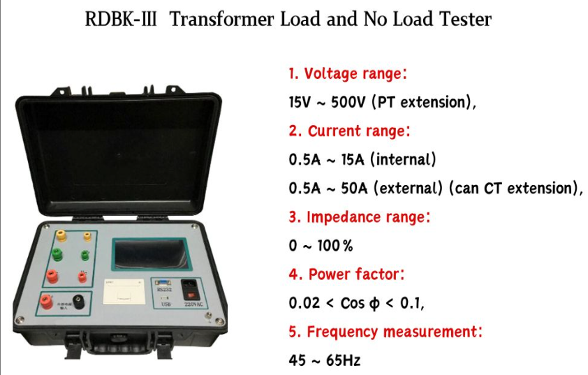
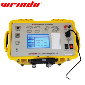
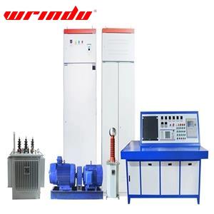
how to calculate no load losses of transformer
Keep each side is empty (not connected to anything);
Keep only the primary side rated voltage;
Measure the input power on the primary side - this is called the no-load loss;
Briefly introduction
Connect the rated voltage (e.g. 220V) to the primary side of the transformer, leave the secondary side unconnected (no connection), and then measure the power consumed by the primary side. This power is basically the no-load loss.
Why? Because the transformer is not loaded at this time, there is no current on the secondary side, so the loss of the coil (copper loss) can be almost ignored. The power consumed is mainly used in the iron core (hysteresis and eddy current loss), which is the bulk of the no-load loss.

Reasons for No-load Loss Test
No-load test is a key link in transformer factory inspection, installation and commissioning, and operation and maintenance. Its core purpose is to evaluate the performance of the transformer core, verify the rationality of the design, and provide an important basis for subsequent operation. The specific reasons are as follows:
1. Evaluation of Core Material and Manufacturing Quality
No-load losses primarily result from hysteresis and eddy current losses in the core, both of which are directly influenced by the core material (such as the purity and magnetic properties of the silicon steel) and the manufacturing process (including lamination flatness, insulation coating quality, and core assembly tightness).
Poor material quality (e.g., excessive impurities in the silicon steel) or damage to the insulation layer during lamination can significantly increase eddy current losses.
If the core is not tightly assembled or there are air gaps, it will increase hysteresis losses.
By conducting no-load testing to measure the loss values, it is possible to quickly identify any quality defects in the core (such as substandard materials or process flaws), ensuring that the transformer core components meet the design standards.
2. Verifying the Rationality of Transformer Design
No-load loss is a crucial parameter during the design phase of a transformer, and it must be validated through testing to ensure that the actual values align with the theoretical calculations:
If the measured loss is significantly higher than the design value, this could indicate issues with the core size, the selection of silicon steel, or the magnetic circuit design (e.g., excessively high flux density), requiring rework or optimization.
If the losses are abnormally low, it is important to check for potential testing anomalies (e.g., insufficient voltage), to avoid misinterpretation of the results.
3. Calculating Transformer Efficiency and Energy Efficiency
The total losses in a transformer consist of no-load losses (core losses) and load losses (copper losses). No-load losses are considered "fixed losses"—they occur regardless of the load size, as long as the transformer is energized.
While the proportion of no-load losses in total losses decreases as load increases, during light load or no-load operation (e.g., distribution transformers at night with low load), no-load losses can become the dominant loss.
By conducting tests to obtain accurate no-load loss values, the efficiency of the transformer at different loads can be calculated (Efficiency = Output Power / Input Power = 1 - Total Losses / Input Power). This allows for the evaluation of its energy-saving performance and compliance with national standards (e.g., energy efficiency rating requirements).
4. Detecting Potential Core Failures
Transformers in operation may experience faults such as multiple grounding points or localized short circuits in the core, leading to a sharp increase in eddy current losses and a significant rise in no-load losses. Therefore:
For new transformers, testing can identify potential hidden defects during manufacturing (e.g., core accidental contact with the casing leading to grounding).
For older transformers, regular no-load tests allow for comparison with historical data, helping to assess whether core aging, insulation degradation, or other issues are occurring, thus preventing further failures (e.g., core overheating and damage).
5. Providing a Basis for Economical Transformer Operation
In power grid planning, no-load losses are an important reference when selecting transformer capacity and type:
For scenarios with long-term light-load operation (e.g., rural grids), transformers with lower no-load losses should be prioritized to reduce long-term energy consumption costs.
Testing data can be used to calculate the "annual loss cost" of a transformer, assisting decision-makers in determining whether to replace outdated equipment with higher losses in order to achieve more cost-effective operation.
6. Compliance with Industry Standards and Regulations
Both international (e.g., IEC 60076) and domestic (e.g., GB 1094.1) standards clearly require transformers to undergo no-load testing before they are shipped or put into operation. Test results must be recorded and archived as proof of product compliance and are a necessary condition for grid acceptance.
Conclusion
The no-load loss test essentially focuses on evaluating the performance of the core, the critical component of a transformer, under a "charged, no-load" condition. This test not only validates product quality and design rationality but also provides data support for assessing transformer efficiency, early fault detection, and cost-effective operation. It is one of the key tests ensuring the safe, efficient, and energy-saving operation of transformers.


