From Principle to Early Warning: Detection and Prediction of Generator Rotor Winding Short Circuit
Questions about Rotor and Stator of Generator
What is the rotor and stator of a generator?
What is the working principle of the rotor in a generator?
What is generator rotor winding?
How do I detect rotor damage and replace it with a new one?
What is the rotor and stator of a generator?
For its definition, the stator of a generator is the stationary component, while the rotor is the rotating component. In most modern generators, the stator is the stationary armature, while the rotor is the rotating conductor that carries the current.
For its function, the stator is typically equipped with three-phase windings. Generators use a rectifier to convert AC power to DC, and a regulator to control the output.
The rotor acts as the "rotating magnetic field carrier" in the generator which can generate a magnetic field through the installation of permanent magnets or excitation windings. As the rotor rotates, it moves relative to the stator, causing the stator magnetic flux to vary over time. This action induces an AC voltage in the stator windings. If the rotor has an excitation winding, a continuous DC excitation current must be supplied to maintain the magnetic field strength. The magnitude of the excitation current directly determines the generator's output capacity and stability. Adjusting the excitation enables voltage and frequency control during grid connection, as well as rapid response to short circuits and load fluctuations. Furthermore, the relationship between speed and output frequency is f = (P/2)*n, and speed stability directly affects the stability of the output voltage and the power quality of the grid.
Therefore, through a stable magnetic field, coupling with the stator magnetic flux, effective excitation control, and precise speed management, the rotor achieves efficient and stable conversion of mechanical energy into electrical energy.
What is the working principle of the rotor in a generator?
The rotor in a generator serves as the rotating magnetic field source. Its working principle can be described in a few connected steps:
Magnetic field source: The rotor carries either permanent magnets or an excitation winding that is fed with DC current. This establishes a magnetic field anchored to the rotor.
Mechanical input: The rotor is coupled to a shaft connected to a mechanical energy source (such as a turbine, engine, or motor). When this shaft is driven, the rotor spins.
Relative motion and flux change: As the rotor rotates, its magnetic field moves relative to the stator windings (the stationary coils surrounding it). This causes the magnetic flux linking the stator to vary over time.
Electromagnetic induction: The changing magnetic flux through the stator windings induces an alternating voltage in the stator coils, according to Faraday's law of electromagnetic induction.
Current and power output: The induced AC voltage drives current in an external circuit. The power extracted from the mechanical input is converted into electrical energy in the stator. And if it's connected to a grid, it will become a part of the electrical power system.
Optional excitation control: If the rotor uses an excitation winding, a DC excitation current is supplied to maintain the magnetic field strength. The excitation level influences the output voltage, current capability, and overall stability of the generator. In grid-connected operation, excitation can be adjusted to regulate voltage and reactive power, and to respond to transient disturbances.
Frequency determination: In a three-phase generator, the output frequency f is related to the rotor speed n by f = (P/2) *n, where P is the number of poles. Therefore, maintaining a stable rotor speed is crucial for voltage and frequency stability.
What is generator rotor winding?
The rotor winding is an insulated conductive coil on the rotor of a motor or generator. It has the core function of establishing a magnetic field on the rotor and interacting with the stator winding to generate power or drive. When an abnormal short circuit occurs in the winding, such as a turn-to-turn short circuit, a phase-to-phase short circuit, or a short circuit to ground, a series of serious problems can occur:
A large inrush current, typically several times the normal operating current (e.g., 2–10 times), flows within the short-circuited coil which will lead to severe heating of the coil and even overheat and do damages to the insulation.
Due to local short circuits and asymmetric electromagnetic fields, three-phase current imbalance occurs. It will cause reduced rotor torque, unstable operation, and even vibration and increased mechanical stress.
The strong electromagnetic shock and thermal stress generated by a short circuit can cause noticeable mechanical noise and vibration, further exacerbating structural damage.
In severe short circuits, the rotor winding cannot provide a stable magnetic field, and the motor or genrtaror may be unable to start under no-load or load conditions, which truly affect system availability.
How do I detect rotor damage and replace it with a new one?
Firstly, we value it by appearance visually. We can look for whether it has physical damage, whether or not it has leaks, whether or not it has blue exhaust smoke and whether or not it has signs of wear, cracking, or discoloration.
Secondly, we value it by auditory and tactile inspection. We try to listen whether it has unusual noises or feet it by excessive vibration.
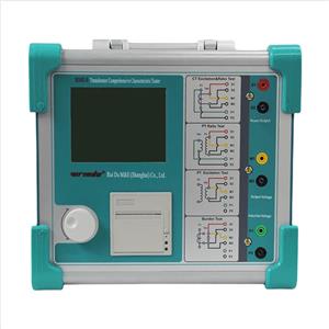
Lastly, after check by the ways above, we can try for electrical testing. Generator rotor AC impedance tester is a special instrument used to determine whether there is an inter-turn short circuit in the generator rotor winding, which can manually and automatically measure many parameters of the generator rotor, such as voltage, current, impedance, power and speed.

RDZZ-605 engine rotor AC impedance tester adopts advanced high-performance microprocessor technology. It can Fully automatic acquisition, measurement, display, storage, and printing of all measurement parameters and impedance characteristic curves (voltage, current, impedance, power, frequency, equipment number, time, etc.). In addition, it can also be used for no-load and short-circuit tests of single-phase transformers and volt-ampere characteristic tests of voltage (current) transformers and arc suppression coils.