DC High Voltage Generator current trends
How to generate high voltage DC?
A traditional method for producing a high DC voltage involves using a step-up transformer constructed with a heavy magnetic core, combined with a Cockcroft-Walton voltage multiplier, which is assembled on an FR4 printed circuit board and occasionally encapsulated in insulating epoxy.
But the current trend of high DC voltage generator is adopting high-frequency voltage doubler circuit, applying the latest PWM pulse width modulation technology and voltage and current double closed-loop feedback technology. In addition, we used imported high-power IGBT devices and their driving technology to eliminate switching interference and achieve high quality and portability of DC high voltage generator. Besides, imported high-frequency and high-voltage rectifier diodes are used to make the voltage doubler more compact and lightweight, thus improving the efficiency of the whole machine.
Now, you may have the question of which technology we have uesd. We will show you by four aspects.
Application Principle
Based on EMI and EMC principles, shielding, isolation, and grounding measures are employed to enhance overall safety so as to withstand rated voltage discharges without damage.
The instrument applies comprehensive protection features, including zero-position protection, overvoltage protection, overcurrent protection, and breakdown protection.
The protection circuit utilizes specialized nanosecond-level sensors. It guarantees rapid and reliable operation, effectively safeguarding personnel and equipment.
Overvoltage setting utilizes a digital DIP switch, offering simple operation and high accuracy. An intelligent, high-precision 0.75U function button facilitates testing of zinc oxide arresters.
High-frequency voltage doubler circuit
A voltage doubler is a circuit that multiplies voltage by a factor of two. It takes an AC voltage as input and generates a DC voltage equal to twice the peak input voltage. This circuit performs two functions: acting as a step-up transformer, increasing the peak AC voltage; and as a rectifier, converting AC to DC. Similar circuits can be cascaded to create tripled, quadrupled, or even higher voltages. A tripler circuit contains three diodes and capacitors, while a quadruple circuit uses four diodes and capacitors. This circuit can be scaled up to any voltage required for a project. A popular trend is the use of high-frequency voltage doubler circuits. The device's main voltmeter directly displays the voltage applied to the load, eliminating the need for an external voltage divider and simplifying wiring. Voltage resolution is 0.1kV, and current resolution is 1uA.
The latest PWM pulse width modulation technology
The fundamental principle of PWM involves controlling the average output voltage by varying the width of the output pulses. With PWM, a constant DC voltage source can produce a sinusoidal output waveform with adjustable frequency and amplitude. This method in the inverter allows for precise regulation of the output voltage waveform in a Voltage Source Inverter (VSI), ensuring accurate control of voltage and current. Additionally, PWM helps to minimize harmonic distortion in the output, thereby enhancing power quality and reducing system losses. Compared to simple square wave modulation techniques, PWM provides superior control over the output voltage, frequency, and harmonic content.
And by explring the Internet, we can get the following ideas. The latest advancements in PWM (Pulse Width Modulation) technology focus on reducing switching losses, improving efficiency, and enhancing control in various applications like motor drives, renewable energy systems, and power supplies. And Its key areas of development include Space Vector Modulation (SVM), Enhanced PWM (EPWM), and random PWM, alongside techniques like adaptive voltage positioning.
Our Products RDZG series applies Space Vector Modulation. Our products utilize an advanced pulse-width modulation technique commonly used in three-phase inverter systems. Compared to other methods, such as 180-degree conduction and SPWM, it offers advantages such as higher power efficiency and lower harmonics. SVM is a digital modulation technique that generates a PWM load-line voltage that averages to a given (or reference) load-line value. Clearly Speaking, you can get useful information from the following figure.
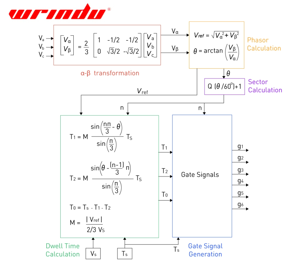
α-β transformation: Using the α-β transformation, the reference three-phase voltages are first represented in a two-dimensional plane. The three-phase voltage space vectors Va, Vb, and Vc are projected onto the α-β plane, yielding a single vector with two components, Vα and Vβ. The formulae for the transformation are illustrated in the alpha-beta transformation block as depicted.
Phasor Calculation: Following that, the Vα and Vβ components are transformed into phasors to estimate their magnitude Vref and angle θ on the α-β plane using the equations in phasor calculation block.
The primary objective of the Space Vector Modulation (SVM) technique is to produce the desired output voltage by strategically selecting appropriate space vectors that correspond to valid switching states and their respective dwell durations—that is, the length of time each vector is applied. By accurately choosing these vectors and their dwell times within a switching period, the overall output voltage can be effectively synthesized, or approximated, in an averaged manner.
The dwell time calculations are guided by equations, which are depicted in the dwell time block. These equations take as inputs the source voltage and the switching period . Using these inputs alongside the reference voltage , the modulation index is determined. The modulation index then serves as a basis to compute the timing durations and for the neighboring valid switching states, as well as , the time spent in the null or zero state.
Since these timing durations must always be positive, the value of the modulation index is constrained to range from 0 up to .
0.75U Function
Our Products applies the intelligent high precision 0.75U function button. If you press this button, the voltage current automatically can be up to the 0.75U state, which is conducive to the oxidation of zinc oxide arrester test.
In summary, RDZG series applies intelligent technology and gets in line with the current trend of DC high voltage generators. If you still have questions, we are willing to provide technical help for you.
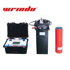
By reading here, if you are interested in RDZG series of DC high Voltage Generator, click here to find more information.
The equipment demonstration video is as follows:
https://www.youtube.com/watch?v=nFhc5ElsygA

