Application of Variable Frequency Series Resonant System in GIS system
Application of Variable Frequency Series Resonant System in GIS system

1.Introduction of variable frequency series resonant withstand voltage test
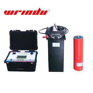
The frequency series resonant withstand voltage test is to use inductance of reactor and capacitance of test object to realize capacitance resonance and obtain high voltage and high current. It is a new method and trend of current high voltage test, and has been widely used at home and abroad. The frequency series resonance is a resonant current filter circuit, which can improve the distortion of power supply waveform, obtain better sinusoidal voltage waveform, and effectively prevent the harmonic peak value from breakdown the test object. When the insulating point of the test object breakdowns, the current immediately detunes, and the loop current rapidly drops to one-tenth of the normal test current. When the flash-over breakdown occurs, the arc can be extinguished because of the loss of resonance condition. Besides the instantaneous decrease of short circuit current, the high voltage also disappears immediately. It takes a longer time to restore the voltage. It is easy to cut off the power supply at flash-over voltage again. So it is suitable for insulation withstand voltage test of high voltage and large capacity power equipment, such as GIS substation, HV crosslinked power cable, generator, large transformer disconnector, transformer, etc.
2. Application of variable frequency series resonance in GIS system
After the GIS is assembled at the factory, the adjustment test of GIS is carried out. After the test is qualified, the GIS is transported to the site for installation. The mechanical vibration and impact in transit may result in loose or relative displacement of fasteners in GIS components or assemblies. In the process of installation, wrong operations in the aspect of connection and sealing lead to scratches on the electrode surface or installation dislocation leads to electrode surface defects. It is difficult to clean up the dust, conductive particles and burrs suspended in the air at the installation site. Due to the limitation of testing equipment and conditions, the field withstand voltage test is not carried out for most of the early GIS products. Accident statistics show that although it cannot be guaranteed that the GIS which has passed the field voltage withstand test will not have insulation accidents in operation, most of the GIS without field AC voltage withstand test have accidents. So, the field withstand voltage test must be done for GIS. The field withstand voltage test of GIS is carried out by alternating current voltage, oscillating lightning impulse voltage of oscillating operating impulse voltage, etc. AC withstand voltage test is a common method in the field withstand voltage test of GIS. It can effectively check the abnormal electric field structure (Such as electrode damage). At present, due to the limitation of test equipment and conditions, only field voltage test is conducted.
(1)Test requirements
① The GIS shall be completely installed. The SF6
Gas shall be charged to the rated density. The resistance measurement of the main circuit, the test of various components, and the test of water content and leakage detection of SF6 gas have been completed. Secondary winding grounding of all current transformers are done, and the secondary voltage winding of the voltage transformer is open and grounded.
②Before the AC withstand voltage test, the following equipment should be isolated from GIS: high-voltage cables and buses; power transformers and most of electromagnetic voltage transformers; lightning arresters and protection spark gap.
③The dielectric test should be made for every new installed part of GIS, and the original part of adjacent equipment should be cut off and grounded when the test is done for extended parts. Otherwise, the sudden breakdown will bring adverse effects to the original equipment.
(2)Method of applying the test voltage
The test voltage is applied to the part between phase conductor and shell; for other non-test phase and shell grounding connection, apply the voltage from
bushings; apply the voltage to each component of GIS at least 1 time in the test. At the same time, in order to avoid the aging of insulation for the same part, the test voltage should be applied to several parts. In general, only phase-to-ground AC withstand voltage test is carried out on site. If the disconnector of the circuit breaker is damaged in transit and installation, or has been disintegrated, the AC dielectric test for the port needs to be performed. The value of withstand voltage is consistent with that of phase-to-ground AC withstand voltage. If the overall capacitance of GIS is large, the withstand voltage test can be carried out in sections.
3. AC dielectric test procedure
The first stage of AC dielectric test in GIS is "sophisticated purification", which aims to remove the conductive or non-conductive particles that may exist in the GIS. These particles may be brought in during installation or metal debris produced after multiple operations, or fastener cutting debris and electrode surface burrs formed. The "sophisticated purification "can make the conductive particles move to the low electric field area or the particle trap and ablate the burr on the electrode surface, so that it cannot damage the insulation. The "experienced purification" voltage value should be lower than the voltage value. The second stage is the dielectric test, that is, after the "sophisticated purification" process, the dielectric test is conducted; the time is 1 min.
4. Judgement of field withstand voltage test results
If each component of the GIS has withstood the specified test voltage without breakdown discharge according to the selected test procedure, the whole GIS is considered to pass the test. If the breakdown discharge occurs during the test, a comprehensive determination should be made according to the discharge energy, various acoustic, optical, electrochemical and other discharge effects caused by the discharge, as well as the test results provided by other fault diagnosis techniques during the withstand voltage test. In case of discharge, the following steps can be taken:
①Apply a specified voltage and repeat the test. If the equipment or gas barrier can withstand, the discharge is self-recovery discharge. If the repeated test voltage reaches the fixed value and specified time, the test product is considered qualified. or the following item will be carried out.
②Disassemble the equipment, open the discharge air gap, and carefully check the insulation condition. After the necessary recovery measures are taken, the next required voltage test can be conducted.
5. Location method of breakdown fault in GIS withstand voltage test
If the interval between the incoming and outgoing lines of the withstand voltage test after GIS segmentation is more, and the non-self-restoring discharge or breakdown occurs during the test, it is difficult to judge the exact location of the fault by the human ear monitoring alone, and it is easy to misjudge and waste manpower, material resources and unnecessary damage to the equipment. The discharge interval can be determined if a fault locator is developed based on the principle of shell vibration caused by shock wave generated by discharge. Before each withstand voltage test, the sensor is respectively installed on the test part, especially on the connecting shell of the circuit breaker, disconnector, bus bar and insulator at the connecting part of each spacer If the discharge or breakdown occurs unpredictably due to the limited number of sensors, the sensor should be moved after the buck and power off according to the monitoring of the discharge, and the voltage should be re-boosted until the discharge or breakdown position is found.