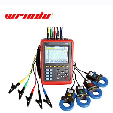
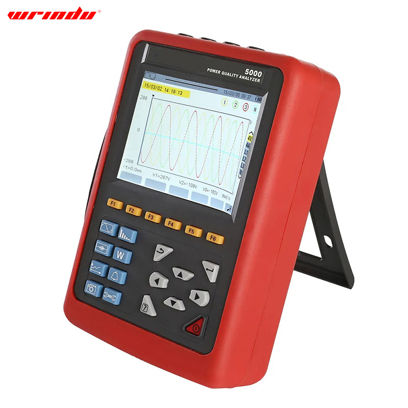
Power Quality Analyzer

- Wrindu
- RDCR5000
1. Dual-processor design: DSP for data, ARM for communication.
2. High-res 16-bit AD7655 analog acquisition at 1 MSPS.
3. DSP > 200 MHz for real-time power grid monitoring.
4. 5.6" color LCD for efficient data visualization.
5. Generous built-in memory for data storage.
Description
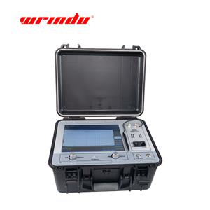
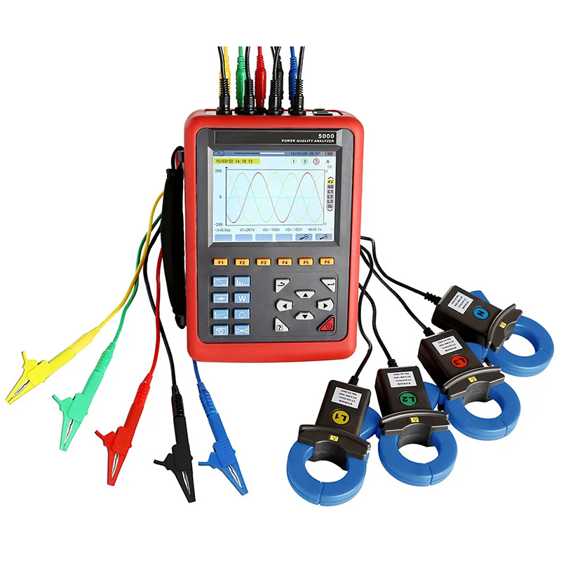
RDCR5000 Power Quality Analyzer is a comprehensive test instrument and specially designed for field test of three phases, multi-functional and intelligent, concise man-machine operation. It is easy to use, large LCD screen display, high resolution, interface in both Chinese and English, shock-proof shell structure and so on. Can simultaneously measure the 4-channel current (ABC three phase and neutral wire current), 4-channel voltage (ABC three-phase voltage and neutral line voltage to ground), the peak value of current voltage, maximum/minimum value over a period, three-phase imbalance factor, short-time voltage flicker, transformer K factor, active power, reactive power, apparent power, power factor and displacement power factor, active power, reactive power, apparent power, total harmonic distortion and harmonic, etc; Display real-time waveform, harmonic ratio bar charts of current voltage; Dynamically capture instantaneous change of voltage current, monitoring starting current, monitoring the power parameters and generate the alarm list, generate the trend chart for a long time record test data.
Features
The analyzer adopt DSP + ARM double processor architecture, DSP is use for data collection and the processing of algorithm, the ARM is use for the communication protocol and the man-machine interface processing;
Analog signal acquisition is by 2 pieces AD7655 of ADI company. Resolution for AD7655 is 16 bit and it is 4 channel synchronous sampling. The highest sampling rate can reach 1 MSPS, to ensure the accuracy of the channel and the information integrity, and wouldn’t miss any transient changes in the grid, can more accurate to detect the transient waveform rising and dropping drastically, and waveform instantaneous interrupt;
DSP working frequency is over 200 MHZ, to be able to timely monitoring of the power grid and dynamically adjust the sampling frequency to realize synchronization of power frequency and sampling frequency;
Using a 5.6 -inch LCD color screen display, a resolution of 640 dots x 480 dots, with different display color difference between the parameters of phase, waveform, vector diagram, harmonic ratio, the user can be more efficient and more intuitive understand the state of power grid parameters.
Built-in flash memory can store 60 group of screenshots at the same time, 150 groups of capture transient voltage/current waveform figure, and 12800 groups of alarm list. Starting current detection model can continuously capture starting current waveform for 100 s.
Built-in 2G memory card to store the trend curve record, simultaneous recording 20 parameters (can choose according to need) collect data for once every five seconds, trend curve records can be stored for 300 days.
Parameters
1. General Specification
Function | Description |
Power supply | Rechargeable lithium-ion battery packs 9.6V, backup charger. |
Battery Level indicator | Battery symbol 5 grid Display power, when the battery level is low, automatically shut down after 1 minute indication |
Working Current | about 590mA, continuous working 8hours. |
Display mode | LCD color screen, 640×480, 5.6 inches, display field 116mm × 88mm |
Instrument Size | 240mm×170mm×68 mm. |
CT Size | 008B small sharp current clamp: 7.5mm×13mm; (optional) 040B round jaw current clamp: 35mm×40mm; (otional) 068B round jaw current clamp: 68mm×68mm. (optional) 300F Flexible Coil Current Sensor (with Integrator) : Ф300mm (optional) |
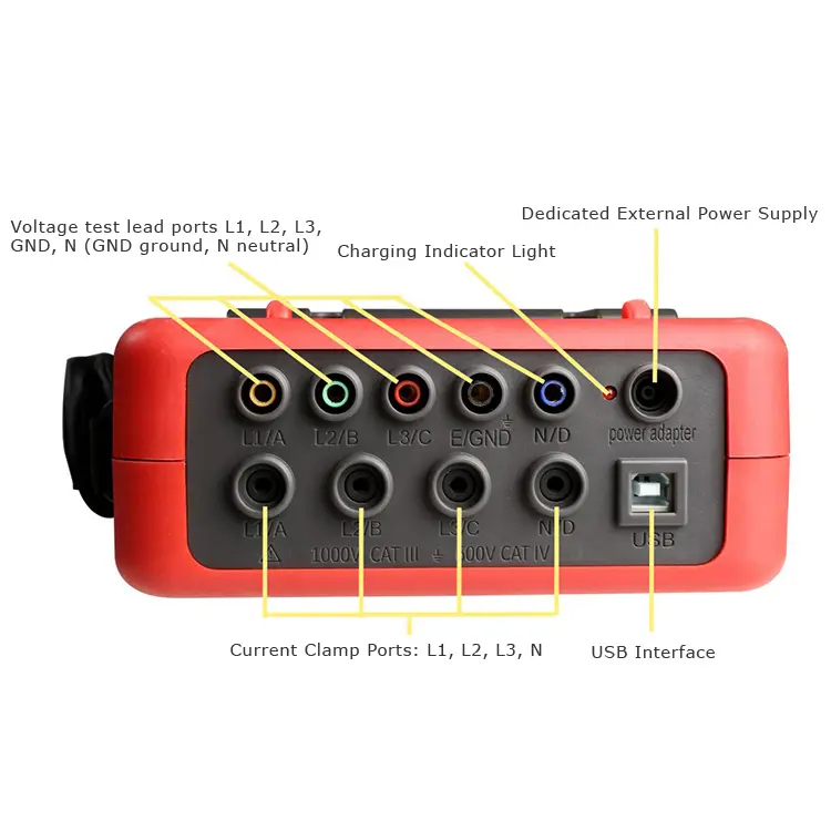
Number of channels | 4 voltages, 4 currents |
Line Voltage | 1.0V~2000V. |
Phase Voltage | 1.0V~1000V. |
Current | 008B small sharp current clamp: 10mA~10.0A; (optional) 040B round jaw current clamp: 0.10A~100A; (optional) 068B round jaw current clamp: 1.0A~1000A; (optional) 300F Flexible Coil Current Sensor (with Integrator) : 10A ~ 6000A (optional) |
Frequency | 40Hz~70Hz. |
Electricity Energy Parameter | W, VA, Var, PF, DPF, cosφ, tanφ. |
Energy parameters | Wh, Varh, Vah. |
Harmonic Wave | Yes, 0 - 50 times |
Total harmonic distortion | Yes, 0 - 50 times, each phase |
Expert Mode | Yes. |
Transient Record Groups | 150 groups |
Voltage Flicker | Yes |
Start Current Mode | Yes, 100 seconds |
Three-phases Unbalance | Yes |
Record | 300 days (record 20 parameters simultaneously, every 5 seconds record 1 point) |
Min/Max Recorded Value | Yes, the max min value can be measured for a certain time |
Alarm | 40 different types of parameter selection, 12800 group alarm logs |
Peak | Yes. |
Phasor Diagram Display | Automatic |
Screenshot Capacity | 60PCS |
Menu language | English/Chinese. |
Communication Interface | USB. |
Automatic Shut Down | In the alarm/trend graph recording/transient capture mode (waiting or in progress), the instrument does not automatically shut down |
In other test modes, there is no button operation within 15 minutes, prompting to automatically shut down after 1 minute. | |
Backlight Function | Yes, suitable for dark places and nighttime use |
Instrument Weight | Host: 1.6kg (with battery). |
008B small sharp current clamp: 170g×4; (optional) | |
040B round jaw current clamp: 190g×4; (optional) | |
068B round jaw current clamp: 510g×4; (optional) | |
300F Flexible Coil Current Sensor (with Integrator) : 330g×4; (optional) | |
Test wires and power adapter: 900g; | |
Total weight: about 9.2kg (with package). | |
Voltage Test Wire Length | 3m |
Current Clamp Wire Length | 2m |
Working Temperature | -10°C~40°C; below 80%Rh. |
Storage Temperature | -10°C~60°C; below 70%Rh. |
Input Impedance | Test voltage input impedance: 1MΩ |
Withstand voltage | Withstand the sine wave AC voltage of 3700V/50Hz one minute between the instrument line and out shell |
Insulation | Between instrument line and shell ≥10MΩ. |
Structure | Double insulation, with insulation shock-proof sheath. |
SuitableSafely Standard | IEC 61010 1000V Cat III / 600V CAT IV, IEC61010-031, IEC61326, Pollution degree: 2. |
2. Instrument Accuracy (excluding the current sensor)
Measurement Specification | Range | Display Resolution | Max Error of Reference Range |
Frequency | 40Hz~70Hz | 0.01Hz | ±(0.03)Hz |
Phase Voltage True RMS | 1.0V~1000V | Min resolution 0.1V | ±(0.5%+5dgt) |
Line Voltage True RMS | 1.0V~2000V | Min resolution 0.1V | ±(0.5%+5dgt) |
DC Voltage | 1.0V~1000V | Min resolution 0.1V | ±(1.0%+5dgt) |
Current True RMS | 10mA~1000A | Min resolution 0.1mA | ±(0.5%+2dgt) |
Phase Voltage Peak | 1.0V~1414V | Min resolution 0.1V | ±(1.0%+5dgt) |
Line Voltage Peak | 1.0V~2828V | Min resolution 0.1V | ±(1.0%+5dgt) |
Current Peak | 10mA~1414A | Min resolution 0.1mA | ±(1.0%+5dgt) |
Peak Factor | 1.00~3.99 | 0.01 | ±(1%+2dgt) |
4.00~9.99 | 0.01 | ±(5%+2dgt) | |
Active Power | 0.000W~9999.9kW | Min resolution 0.001W | ±(1%+3dgt); Cosφ≥0.8 |
±(1.5%+10dgt); 0.2≤Cosφ<0.8 | |||
Reactive power Inductive& Capacitive | 0.000Var~9999.9kVar | Min resolution 0.001Var | ±(1%+3dgt);Sinφ≥0.5 |
±(1.5%+10dgt); 0.2≤Sinφ<0.5 | |||
Apparent Power | 0.000VA~9999.9kVA | Min resolution 0.001VA | ± (1%+3dgt %) |
Power Factor | -1.000~1.000 | 0.001 | ±(1.5%+3dgt); Cosφ≥0.5 |
±(1.5%+10dgt); 0.2≤Cosφ<0.5 | |||
Active Energy | 0.000Wh~9999.9MWh | Min resolution 0.001Wh | ±(1%+3dgt); Cosφ≥0.8 |
±(1.5%+10dgt); 0.2≤Cosφ<0.8 | |||
Reactive Energy Inductive& Capacitive | 0.000Varh~9999.9MVarh | Min resolution 0.001Varh | ±(1%+3dgt);Sinφ≥0.5 |
±(1.5%+10dgt); 0.2≤Sinφ<0.5 | |||
Apparent Energy | 0.000VAh~9999.9MVAh | Min resolution 0.001VAh | ±(1%+3dgt) |
Phase Angle | -179°~180° | 1° | ±(2°) |
Tanφ(VA≥50VA) | -32.768~32.768 | Min resolution 0.001 | ±(1%+5dgt) |
Displacement Power Factor(DPF) | -1.000~1.000 | 0.001 | ±(1%+5dgt) |
HarmonicRatio (Vrms>50V) | 0.0 %~99.9 % | 0.1 % | ±(1%+5dgt) |
Harmonic Angle(Vrms >50V) | -179°~180° | 1° | ±(3°)harmonic1~25 |
±(10°)harmonic26~50 | |||
Total Harmonic Rate (DF or THD-F)≤50 | 0.0 %~99.9 % | 0.1 % | ±(1%+5dgt) |
Distortion Factor (DF or THD-R)≤50 | 0.0 %~99.9 % | 0.1 % | ±(1%+10dgt) |
Transformer K Factor | 1.00~99.99 | 0.01 | ±(5 %) |
Three-phase Unbalance | 0.0%~100 % | 0.1 % | ±(1 %) |
Note: The following data are presented in reference conditions and ideal current sensors (completely linear and without phase displacement)
3. Current Sensor Characteristics (Optional)
Current sensor model | Current Clamp | Current True RMS | Current True RMS Max Error | Phase Angle φ Max Error |
008B small sharp current clamp: 7.5mm×13mm |
| 10mA~99mA | ±(1%rdg+3dgt) | ±(1.5°),Arms≥20mA |
100mA~10.0A | ±(1%rdg+3dgt) | ±(1°) | ||
040B round jaw current clamp:Ф40mm |
| 0.10A~0.99A | ±(1%rdg+3dgt) | ±(1.5°) |
1.00A~100A | ±(1%rdg+3dgt) | ±(1°) | ||
068B round jaw current clamp:Ф68mm |
| 1.0A~9.9A | ±(2%rdg+3dgt) | ±(3°) |
10.0A~1000A | ±(2%rdg+3dgt) | ±(2°) | ||
300F Flexible Coil Current Sensor:Ф300mm |
| 10A~99A | ±(1%rdg+3dgt) | ±(3°) |
100A~6000A | ±(1%rdg+3dgt) | ±(2°) |


Note: the above four current sensors are selected by users according to their own needs. (If not, selected R068B round jaw current clamp by default)