Navigating the Electrical Realm: Differences in Insulation and Ground Resistance

What is this content about:
1. Introduction to Insulation Resistance
2. Introduction to Ground Resistance
3. Differences Between Insulation Resistance and Ground Resistance
Introduction to Insulation Resistance
Insulation resistance is a fundamental indicator for electrical equipment and circuits. For the routine testing of
low-voltage electrical devices, the insulation resistance of motors, distribution equipment, and distribution lines
at room temperature should not be less than 0.5 MΩ (for equipment and lines in operation, insulation resistance
should not be less than 1 MΩ per kilovolt). The insulation resistance of low-voltage appliances, connecting
cables, and secondary circuits should generally not be less than 1 MΩ, and in relatively humid environments, it
should not be less than 0.5 MΩ. The insulation resistance of secondary circuit small busbars should not be less
than 10 MΩ. The insulation resistance of Class I hand-held power tools should not be less than 2 MΩ.
1. Factors Affecting Insulation Resistance:
1.1 Environmental Temperature and Humidity
The insulation resistance of common materials generally decreases with an increase in environmental
temperature and humidity. Surface resistance (ratio) is more sensitive to environmental humidity, while bulk
resistance (ratio) is more sensitive to temperature. An increase in humidity leads to increased surface leakage,
and higher temperatures accelerate the movement of charge carriers, increasing absorption and conduction
currents. Therefore, when measuring insulation resistance, it is crucial to specify the temperature and humidity
at which the sample reaches equilibrium with the environment.
1.2 Test Duration
When applying a DC voltage to the tested material, the current does not instantly reach a stable value; it
undergoes a decay process. The current experiences a large charging current initially, followed by a slow
decrease in absorption current over a relatively long time, eventually reaching a stable conductive current.
The higher the resistance being measured, the longer it takes to reach equilibrium. Therefore, to obtain
accurate resistance values, readings should be taken after the system stabilizes.
1.3 Cable Self-Factors
The insulation material ages and loses insulation resistance when exposed to heat and moisture.
Insulation Resistance Measurement Methods:
Megohmmeter Method - Suitable for measuring the insulation resistance of insulation joints (flanges) not
installed on pipes. Connect the circuits according to the megohmmeter method, ensuring good contact between
the measurement wire and the pipe using magnetic connectors or clips, removing any rust from the connection
points. Use a 500V, 500 MΩ (error should not exceed ten percent) megohmmeter, rotate the handle at the
specified speed for 10 seconds, and the stable resistance value indicated by the megohmmeter is the insulation
resistance of the insulation joint (flange), required to be greater than 10 MΩ.
Introduction to Ground Resistance
Ground resistance is the resistance encountered by current as it flows into the ground from the grounding
device and then disperses into another grounding body or diffuses into the distance. Ground resistance values
reflect the quality of electrical devices' contact with the ground and indicate the scale of the grounding grid.
1. Factors Affecting Ground Resistance:
Various factors influence ground resistance, including the size (length, thickness), shape, quantity, burial depth,
surrounding geographical environment (flat ground, trenches, slopes), soil moisture, texture, etc. To ensure
proper grounding, measuring ground resistance using instruments is essential.
2. Methods for Ground Resistance Measurement:
Factors such as inconsistent soil composition around the grounding grid, varied geological conditions, different
levels of compaction, and the presence of stray currents (especially from overhead wires, underground
pipelines, cable sheaths, etc.) can significantly impact test results. To address this, measurements should be
taken at different points, and the average value should be considered.
3. Factors Affecting Accuracy in Ground Resistance Measurement:
3.1 Inconsistent soil composition around the grounding grid, varying geological conditions, compaction levels, and
differences in surface moisture can lead to dispersed effects on testing. Solution: Measure at different points
and take an average.
3.2 Incorrect test line direction or insufficient length. Solution: Ensure the correct test direction and sufficient
distance.
3.3 Excessive resistance in auxiliary grounding electrodes. Solution: Apply water or use a resistance-reducing
agent to lower the resistance at the current electrode.
3.4 Excessive contact resistance between the test clamp and the grounding measurement point. Solution: Polish
the contact points with a file or sandpaper and ensure a secure grip with the polished points.
3.5 Interference issues. Solution: Adjust the line direction to avoid significant interference, reducing instrument
reading fluctuations.
3.6 Instrument usage problems. Low battery levels can be addressed by replacing the battery, and if the
instrument's accuracy is compromised, recalibration to zero is necessary.
The accuracy of ground resistance test values is a crucial factor in determining the adequacy of grounding.
Inaccurate values can lead to resource wastage (overestimated values) or pose safety risks to grounding
equipment (underestimated values).
Differences Between Insulation Resistance and Ground Resistance
Differences Between Insulation Resistance and Ground Resistance
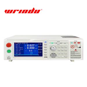
Insulation resistance measures the insulation level between wires, cables, interlayers, and neutral points. A
higher test value indicates better insulation performance, and RD3215E Insulation Resistance T ecan be used
for measurement.
Ground resistance measures the effectiveness of electrical devices connecting to the ground. It reflects the
tightness of contact between conductors or lightning rods and the earth, including the resistance of grounding
wires and grounding bodies, contact resistance between grounding bodies and the earth, and the earth
resistance between two grounding bodies or to an infinite distance. The magnitude of ground resistance directly
reflects the degree of contact between electrical devices and the ground and indicates the scale of the
grounding grid. The concept of ground resistance is suitable for small grounding grids. As the area occupied
by the grounding grid increases and soil resistivity decreases, the inductive component in the ground
impedance becomes more significant. In such cases, large grounding grids should use ground impedance
design.
1. Ground Resistance Measurement Methods:
Factors affecting ground resistance are numerous, such as the size of the grounding electrode (length,
thickness), shape, quantity, burial depth, surrounding geographical environment (flat ground, trenches,
slopes), soil moisture, texture, etc.
To ensure proper equipment grounding, measuring ground resistance is essential. Ground resistance
measurement methods incluthe de voltage-current meter method, ratio method, and bridge method.
Depending on the specific measurement instrument and polar configuration, it can be divided into
hand-cranked ground resistance meter method, clamp ground resistance meter method, voltage-current
meter method, three-pole method, and four-pole method.
During ground resistance measurement, some factors may lead to inaccurate readings:
1. Inconsistent soil composition around the grounding grid, different geological conditions, varying
compaction levels, and differences in surface moisture. Solution: Measure at different points and take an
average.
2. Incorrect test line direction or insufficient length. Solution: Ensure the correct test direction and sufficient
distance.
3. Excessive resistance in auxiliary grounding electrodes. Solution: Apply water or use a resistance-reducing
agent to lower the resistance at the current electrode.
4. Excessive contact resistance between the test clamp and the grounding measurement point. Solution: Polish
the contact points with a file or sandpaper and ensure a secure grip with the polished points.
5. Interference issues. Solution: Adjust the line direction to avoid significant interference, reducing instrument
reading fluctuations.
6. Instrument usage problems. Low battery levels can be addressed by replacing the battery, and if the
instrument's accuracy is compromised, recalibration to zero is necessary.
Insulation Resistance Testing Principle:
When measuring insulation resistance, a DC voltage U is applied to the insulating material. At this point, the
current undergoes a decaying process over time, usually a combination of capacitive current, absorption
current, and conductive current. The capacitive current Ic decays rapidly, absorption current Iaδc decays
much slower, and conductive current Inp stabilizes relatively quickly. If the insulation is dry and the surface
is clean, the transient current components Ic and Iaδc quickly decay to zero, leaving only a small conductive
current Inp.
As the insulation resistance is inversely proportional to the current flow, the insulation resistance rises rapidly
and stabilizes at a high value. Conversely, if theinsulation is moist, the conductive current significantly
increases, even surpassing the initial value of absorption current Iaδc.
The transient current components decrease significantly, and the insulation resistance value appears low,
changing minimally over time. Therefore, in insulation resistance tests, absorption ratio is typically used to
assess the moisture condition of insulation. When the absorption ratio is greater than 1.3, it indicates good
insulation, while a ratio close to 1 suggests moisture in the insulation. Electronic megohmmeters are suitable
for measuring cables, wires, transformers, motors, and other electrical equipment.
Ground Resistance Tester Principle:
The ground resistance value Rx is obtained by applying a constant AC current I between the E (grounding
electro H (C) (power supply electrode) of the measured object, and observing the potential difference V
between E (grounding electrode) and S (P) (measuring electrode).